- Long Delay Timer Circuit: 35 Minute Battery-Powered Design
- Build Your Custom 3-9 Minute Beep Timer Circuit
- Build Your Amplifier Timer Circuit – 15 Minute Delay
- Timed Beeper Circuit: Build Your Precise Timer!
- Build Your 30-Minute Bedside Lamp Timer Circuit
- Time Delay Circuit: Build Your Appliance Protector
- Midnight Security Light Circuit: A 1:00 AM Intrusion Defense
- Delay Relay Circuit: 12V, 15s
- Build a Powerful 1300W Space Heater Circuit Diagram
- Building a 1-Second Delayed Pulse with the 555 Timer
- 555 Timer Mono Stable Circuit Design & Build Guide
- Build Precise Time Delays with a 12-Stage Binary Counter
- Time Delay Circuit: 5A Output from Low Voltage Batteries
- Build a Powerful 1300W AC Heater Circuit Design
- Build Your 9-Second LED Timer & Relay Circuit 9V
Adjustable Interval Timer: Build Your Precise Timing Circuit
The use of an on-board relay to switch mains voltage is strictly prohibited. The board’s layout does not offer sufficient isolation between the relay contacts and the low-voltage components. If mains voltage switching is required - a suitably rated relay must be mounted externally - Away From The Board. I have employed a SPCO/SPDT relay - but a multi-pole relay may be used if desired.
Description:
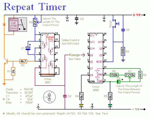
This circuit incorporates an adjustable output timer, capable of re-triggering at intervals ranging from a fraction of a second to half an hour or beyond. The output period can be configured to recur at regular intervals, spanning from seconds to days.
Circuit diagram
The Output Section:
The output section utilizes a monostable circuit. When Pin 6 of the Cmos 4001 is activated, the monostable circuit triggers, and the relay energizes. The relay remains energized for a duration determined by the values of C1 and R3. With the specified component values, R3 provides output periods extending up to approximately 30 minutes. However, component values can be selected to suit particular requirements. For instance, reducing R3 to 1 megaohm and C1 to 4.7 microfarads results in a maximum output period of between 3 and 5 seconds. Due to manufacturing tolerances, the precise length of the time period depends on the characteristics of the particular components utilized.
The Cmos 4060:
The Cmos 4060 is a 14-bit binary counter with an integrated oscillator. The oscillator consists of two inverters connected to Pins 9, 10 and 11, and its frequency is controlled by R7. The output from the oscillator is internally connected to the binary counter. While the oscillator is running, the IC counts oscillations, and the state of the count is reflected in the output pins. By adjusting R7, the length of time it takes for any given output pin to go high can be set. Connecting that output to Pin 6 of the Cmos 4001 and every time it goes high, it triggers the monostable. Ideally, C4 should be non-polarized - but a regular electrolytic will function, provided it does not leak excessively in the reverse direction. Alternatively, a non-polarized 10 microfarad capacitor can be simulated by connecting two 22 microfarad capacitors back to back, as illustrated.
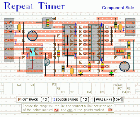
Veroboard Layout:
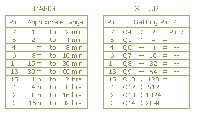
Due to the potential for delays lasting hours or even days, utilizing "trial and error" to set up the timer would prove exceedingly tedious. A more efficient solution involves utilizing the Setup Table and calculating the required time for Pin 7 of the Cmos 4060 to activate. For example, if the monostable is desired to trigger every six hours - the Range Table indicates that Pin 1 of the Cmos 4060 should be used. This requires Pin 1 to go high every 6 x 60 x 60 seconds, which is 21,600 seconds. The Setup Table specifies that for Pin 1, dividing this figure by 512 yields approximately 42 seconds. Adjusting R7 ensures that the Yellow LED illuminates 42 seconds after power application, triggering Pin 1 to go high after roughly 3 hours.
Setup Tables:
When Pin 1 goes high, it remains high for three hours. Subsequently, it goes low for three hours before returning to the high state. Consequently, Pin 1 goes high every six hours. The act of going high is what triggers the monostable. Therefore, following an initial delay of three hours, the relay will energize. It will then re-energize every six hours thereafter. The reset button should NOT be employed during the setup process. The time it takes for Pin 7 to go high and the Yellow LED to illuminate - must be measured from the moment power is applied. Although R4, R5 and the two LEDs assist in the setup - they are not essential to the timer's operation. If reduced power consumption is desired - disconnect them once the setup is complete. The timer is designed for a 12-volt supply - however, with a suitable relay, it operates across a range of 5 to 15 volts. Applying power initiates the timer - and it can be reset at any time through a brief interruption of the power supply. Therefore, a reset button is not strictly necessary. For delays exceeding 32 hours - increase the value of C4. The Support Material for this circuit includes a step-by-step guide to the construction of the circuit-board - a parts list - a detailed circuit description - and more.
circuit from http://www.zen22142.zen.co.uk/


