- Long Delay Timer Circuit: 35 Minute Battery-Powered Design
- Build Your Custom 3-9 Minute Beep Timer Circuit
- Build Your Amplifier Timer Circuit – 15 Minute Delay
- Timed Beeper Circuit: Build Your Precise Timer!
- Build Your 30-Minute Bedside Lamp Timer Circuit
- Time Delay Circuit: Build Your Appliance Protector
- Midnight Security Light Circuit: A 1:00 AM Intrusion Defense
- Delay Relay Circuit: 12V, 15s
- Build a Powerful 1300W Space Heater Circuit Diagram
- Building a 1-Second Delayed Pulse with the 555 Timer
- 555 Timer Mono Stable Circuit Design & Build Guide
- Build Precise Time Delays with a 12-Stage Binary Counter
- Time Delay Circuit: 5A Output from Low Voltage Batteries
- Build a Powerful 1300W AC Heater Circuit Design
- Build Your 9-Second LED Timer & Relay Circuit 9V
Build Your Own: 100s Delayed & Multi-Range Relay Timers
Description
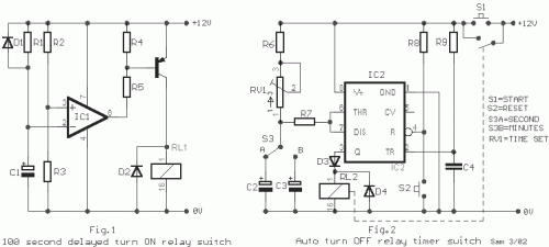
Fig.1 illustrates a 100 millisecond delayed activation switch for relay RL1, activated upon connection of the +12V power supply. Fig.2 depicts a dual-range circuit, offering both a 6-60 second and a 1-10 minute automatic deactivation timer functionality, incorporating the LM555 integrated circuit.
Circuit diagram
Part List
- R1=1 Mohms
- R2=330 Kohms
- R3=680 ohms
- R4=2.2 Kohms
- R5-7=4.7 Kohms
- R6=47 Kohms
- R8-9=22 Kohms
- C4=100nF 63V
- C1-2=100uF 16V
- C3=1000uF 16V
- D1=1N4148
- D2-3-4=1N4001
- Q1=BC214
- IC1=LM741
- IC2=LM555
- RV1=470 Kohms pot.
- RL1-2=12V >120 ohms Relay
- S1-2=Push button n.o
- S3=2X2 switch
LM555 Integrated Circuit
The LM555 is a versatile integrated circuit predominantly utilized as a timer, oscillator, or multivibrator. It's characterized by its ability to generate accurate time delays or trigger oscillating waveforms, making it indispensable in a myriad of electronic circuits. This particular IC is employed here to control the timing of the auto-turn off timer function.
LM741 Integrated Circuit
The LM741 is a widely utilized operational amplifier (op-amp) known for its high gain and stable performance. This integrated circuit serves as the main amplifier within the circuit, crucial for signal amplification and achieving the desired circuit behavior. It’s a cornerstone component in many analog circuit designs, offering excellent linearity and precision.
