- Long Delay Timer Circuit: 35 Minute Battery-Powered Design
- Build Your Custom 3-9 Minute Beep Timer Circuit
- Build Your Amplifier Timer Circuit – 15 Minute Delay
- Timed Beeper Circuit: Build Your Precise Timer!
- Build Your 30-Minute Bedside Lamp Timer Circuit
- Time Delay Circuit: Build Your Appliance Protector
- Midnight Security Light Circuit: A 1:00 AM Intrusion Defense
- Delay Relay Circuit: 12V, 15s
- Build a Powerful 1300W Space Heater Circuit Diagram
- Building a 1-Second Delayed Pulse with the 555 Timer
- 555 Timer Mono Stable Circuit Design & Build Guide
- Build Precise Time Delays with a 12-Stage Binary Counter
- Time Delay Circuit: 5A Output from Low Voltage Batteries
- Build a Powerful 1300W AC Heater Circuit Design
- Build Your 9-Second LED Timer & Relay Circuit 9V
Timed Beeper: Build a 7.5s Delay Timer Circuit
Beeps 7.5 seconds after a preset time
Adjustable time settings: 15 sec. 30 sec. 1 min. 2 min. & others
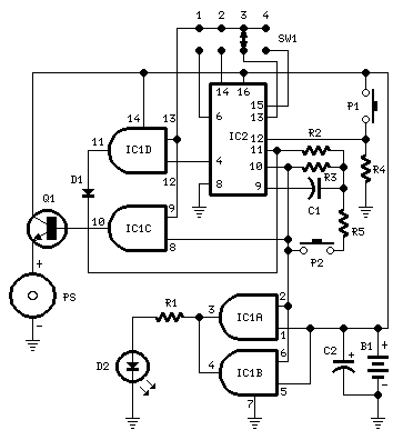
Circuit diagram
Parts:
- R1 220Ω 1/4W Resistor
- R2 10MΩ 1/4W Resistor
- R3 1MΩ 1/4W Resistor
- R4 10kΩ 1/4W Resistor
- R5 47kΩ 1/4W Resistor
- C1 100nF 63V Polyester Capacitor
- C2 22µF 25V Electrolytic Capacitor
- D1 1N4148 75V 150mA Diode
- D2 3mm. Red LED
- IC1 4081 Quad 2 input AND Gate IC
- IC2 4060 14 stage ripple counter and oscillator IC
- Q1 BC337 45V 800mA NPN Transistor
- P1 SPST Pushbutton (Start)
- P2 SPST Pushbutton (Reset)
- SW1 4 ways Switch (See notes)
- PS Piezo sounder (incorporating 3KHz oscillator)
- B1 3V Battery (2 AA 1.5V Cells in series)
Device purpose:
This circuit is intended for alerting applications following a defined duration. It is suitable for game sessions needing a fixed time to answer a question, or to move a piece, etc. In this regard, it represents a modern alternative to the traditional sandglass. It's also beneficial for time monitoring during children's tooth brushing (at least two minutes!), or in the kitchen, and so on.
Circuit operation:
Pushing P1 initiates the oscillation of IC2 at a frequency determined by R3 and C1. With the specified values, this frequency is approximately 4Hz. The LED D2, powered by IC1A and B, flashes at the same oscillator frequency, indicating proper circuit operation. SW1 selects the appropriate pin of IC2, thereby adjusting the timing duration as follows:
- Position 1 = 15 seconds
- Position 2 = 30 seconds
- Position 3 = 1 minute
- Position 4 = 2 minutes
When the selected pin of IC2 goes high, IC1C drives Q1 and the piezo sounder emits intermittent beeps at the same frequency as the LED. After approximately 7.5 seconds, pin 4 of IC2 goes high, and IC1D terminates the oscillator via D1. To halt the counting prematurely, push P2.
Notes:
- SW1 can be any type of switch with the desired number of positions. If a single fixed timing duration is desired, omit the switch and connect pins 9 and 13 of IC1 to the appropriate pin of IC2.
- The circuit's reset is not immediate. Pushing P2 forces IC2 to oscillate very rapidly, but it takes several seconds to finalize the counting, particularly when longer durations are chosen, and the pushbutton is activated immediately after the circuit has begun. To expedite the reset, consider lowering the value of R5, although be mindful: excessively low values can disrupt the oscillation.
- Frequency operation can vary depending on the manufacturer of IC2. For example, Motorola ICs tend to operate at a faster frequency, necessitating adjustments to C1 and/or R3 values.
- The IC2 pins 1, 2, and 3 can also be used to achieve timings of 8, 16, and 32 minutes respectively.
- An on-off switch is not provided, as the circuit consumes minimal current in the off state.
Integrated Circuits Detail: IC1
IC1 (4081 Quad 2 input AND Gate IC)
The 4081 is a quad AND gate integrated circuit. This chip consists of four independent AND gates, allowing for versatile logic circuit design. Each gate accepts two inputs and produces one output, governed by the logical AND operation. This IC simplifies the circuit design and reduces the number of discrete components required.
Integrated Circuits Detail: IC2
IC2 (4060 14 stage ripple counter and oscillator IC)
The 4060 is a 14-stage ripple counter and oscillator integrated circuit. It’s commonly used for generating precise time delays. The design features a cascade of flip-flops, each contributing to the overall delay. The output signal is derived from the final stage, allowing for accurate time measurements based on the counter’s state. It is a common component in timing circuits due to its simplicity and reliability.
circuit from http://www.redcircuits.com/
