- Boost Your MP3 Power: 32 Ohm Amplifier Circuit
- Build Your 9V Bass Booster Circuit Diagram
- Build Your 20dB Audio Booster Circuit Diagram
- Symmetrical Class A Preamplifier – Build Your Audio Masterpiece
- Build Your Perfect Symmetrical 4 Channel Amplifier Circuit
- Build Your Ideal Buffer: Class A Circuit Diagram (560Ω)
- Discrete Preamplifier Circuit Diagram
- Build Your Own: Microphone Preamplifier Circuit (2mA)
- Stereo Preamplifier Circuit: Build Your +16dB Bass Boost
- Phono Preamplifier Circuit Diagram: 47K, 6.8K, 47nF Build!
- Modular Preamplifier Switching Center: Build Your Stereo Chain
- Portable Microphone Preamplifier Circuit Diagram – Build Your Own!
- Build Your Own Phono Preamplifier Circuit (18V)
- Amplify Signals: 741 Op-Amp Stethoscope Circuit Diagram
- Turn Speaker into Microphone: Build Your 6-12V Circuit
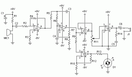
Amplify Signals: 741 Op-Amp Stethoscope Circuit Diagram
Description
Medical devices are not exclusively for medical professionals; home technicians, pest control specialists, surveillance operations, and a diverse range of applications benefit from their utilization. Conventional stethoscopes lack amplification capabilities, thereby restricting their effectiveness. This circuit employs operational amplifiers to significantly boost a standard stethoscope’s signal, incorporating a low-pass filter to attenuate extraneous sounds.
More about components
Operational amplifiers, commonly referred to as op-amps, are versatile integrated circuits that significantly enhance electronic circuits. The 741 series, featured in this design, is a widely utilized dual op-amp IC. These circuits provide amplification and signal processing functionalities, making them ideal for audio applications, signal conditioning, and numerous other electronic systems. Their differential input configuration allows for precise signal manipulation, improving the overall performance of the stethoscope amplifier circuit.
Circuit diagram
Parts:
- R1 10K 1/4W Resistor
- R2, R3, R9 2.2K 1/4W Resistor
- R4 47K 1/4W Resistor
- R5, R6, R7 33K 1/4W Resistor
- R8 56K 1/4W Resistor
- R10 4.7K 1/4W Resistor
- R11 2.5K Pot
- R12 330K 1/4W Resistor
- R13 1K 1/4W Resistor
- R14 3.9 Ohm 1/4W Resistor
- C1 470uF Electrolytic Capacitor
- C2, C3, C4 0.047uF Capacitor
- C5 0.1uF Capacitor
- C6 1000uF Electrolytic Capacitor
- D1 Bi-Colour LED
- U1, U2, U3, U4, U5 741 Op-Amp
- MIC1 Electret Mic
- J1 1/4" Phone Jack
- MISC Board, Wire, Sockets for ICs, Knob for pot, Stethoscope, Rubber tube
Notes:
- MIC1 constitutes an assembly combining a stethoscope head and an electret microphone. Remove the head from the stethoscope and connect the nipple to the microphone utilizing a short piece of rubber tubing.
- Exercise caution regarding volume levels to prevent potential damage to hearing.
- The positive and negative terminals of the 9V power supply can be provided by two 9V batteries connected in series, with the connection made at their common junction.
- R11 serves as the volume control.
