- Boost Your MP3 Power: 32 Ohm Amplifier Circuit
- Build Your 9V Bass Booster Circuit Diagram
- Build Your 20dB Audio Booster Circuit Diagram
- Symmetrical Class A Preamplifier – Build Your Audio Masterpiece
- Build Your Perfect Symmetrical 4 Channel Amplifier Circuit
- Build Your Ideal Buffer: Class A Circuit Diagram (560Ω)
- Discrete Preamplifier Circuit Diagram
- Build Your Own: Microphone Preamplifier Circuit (2mA)
- Stereo Preamplifier Circuit: Build Your +16dB Bass Boost
- Phono Preamplifier Circuit Diagram: 47K, 6.8K, 47nF Build!
- Modular Preamplifier Switching Center: Build Your Stereo Chain
- Portable Microphone Preamplifier Circuit Diagram – Build Your Own!
- Build Your Own Phono Preamplifier Circuit (18V)
- Amplify Signals: 741 Op-Amp Stethoscope Circuit Diagram
- Turn Speaker into Microphone: Build Your 6-12V Circuit
Build Your 20dB Audio Booster Circuit Diagram
Description
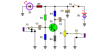
The amplifier’s gain is approximately 20 dB. The circuit’s performance characteristics are mainly dictated by the values of only a select number of components – most notably C1 and R1. The chosen values within the schematic diagram yield a response of ±3.0 dB across a frequency range of roughly 120 Hz to beyond 20,000 Hz. In reality, the frequency response is remarkably flat between approximately 170 Hz and substantially over 20,000 Hz; deviations from a uniform frequency response occur at the lower end. The lower frequencies exhibit a gradual decline in response, and this is principally determined by the capacitance C1 (as the resistive value of R1 remains constant). Should C1 be altered to 0.1 pF, the corner frequency of the lower frequencies – the point at which the lower-end roll-off commences – is reduced to approximately 70 Hz. For an even more pronounced attenuation in the low-end, consider substituting C1 with a 1.0 µF capacitor; if it's an electrolytic type, it must be installed into the circuit with the correct polarity, with the positive terminal connected to Q1’s base terminal.
Circuit diagram:
Parts:
- P1 = 100K
- R1 = 47K
- R2 = 470K
- R3 = 10K
- R4 = 560R
- R5 = 270R
- C1 = 0.1uF-25v
- C2 = 3.3uF-25v
- C3 = 470uF-25V
- D1 = 5mm. Red Led
- B1 = 9v Battery
- J1 = RCA Audio Input Socket
- J2 = RCA Audio Output Socket
- S1 = On-Off Switch
