- Boost Your MP3 Power: 32 Ohm Amplifier Circuit
- Build Your 9V Bass Booster Circuit Diagram
- Build Your 20dB Audio Booster Circuit Diagram
- Symmetrical Class A Preamplifier – Build Your Audio Masterpiece
- Build Your Perfect Symmetrical 4 Channel Amplifier Circuit
- Build Your Ideal Buffer: Class A Circuit Diagram (560Ω)
- Discrete Preamplifier Circuit Diagram
- Build Your Own: Microphone Preamplifier Circuit (2mA)
- Stereo Preamplifier Circuit: Build Your +16dB Bass Boost
- Phono Preamplifier Circuit Diagram: 47K, 6.8K, 47nF Build!
- Modular Preamplifier Switching Center: Build Your Stereo Chain
- Portable Microphone Preamplifier Circuit Diagram – Build Your Own!
- Build Your Own Phono Preamplifier Circuit (18V)
- Amplify Signals: 741 Op-Amp Stethoscope Circuit Diagram
- Turn Speaker into Microphone: Build Your 6-12V Circuit
Symmetrical Class A Preamplifier – Build Your Audio Masterpiece
Description
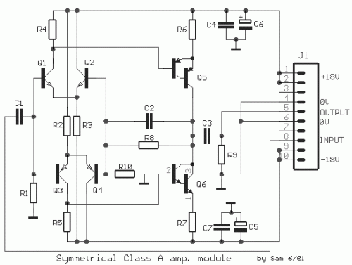
A straightforward and effective amplification unit, exhibiting minimal distortion. A comparable alteration was implemented as a preamplifier by HAFLER. Nevertheless, the fidelity of the audio signal produced across all symmetrical circuits, irrespective of the materials utilized – transistors, capacitors, and resistors – remained a persistent challenge.
Circuit Diagram
Part List
- R1= 100Kohm
- R2-3= 82Kohm
- R4-5= 22Kohm
- R6-7= 100ohm
- R8= 5.6Kohm
- R9= 100Kohm
- R10= 1Kohm
- C1-3= 10uF MKT
- C2= 56pF ceramic
- C4-5= 100nF 63V
- C6-7= 47uF 40V
- T1-2= BC 550C
- T3-4= BC 560C
- T5= BC 516
- T6= BC 517
More about components
The BC 550C, BC 560C, BC 516, and BC 517 are all examples of bipolar junction transistors (BJTs) which are commonly used in amplification and switching circuits due to their ability to control current flow with a small applied voltage. They are essential building blocks in many electronic systems. These transistors utilize current flow between their collector and emitter terminals to produce an amplified output signal or perform switching operations. The small signal variations are amplified in the transistor’s base-emitter junction. The specific characteristics of these transistors – such as their current gain and voltage-to-current conversion ratio – determine their suitability for various applications.
Warnings
Incorrect wiring or component selection can damage the amplifier unit. Always double-check your connections before applying power. Modifications to this circuit are undertaken entirely at the user’s own risk. The author and source of this circuit diagram are: [Link to Source].
