- Boost Your MP3 Power: 32 Ohm Amplifier Circuit
- Build Your 9V Bass Booster Circuit Diagram
- Build Your 20dB Audio Booster Circuit Diagram
- Symmetrical Class A Preamplifier – Build Your Audio Masterpiece
- Build Your Perfect Symmetrical 4 Channel Amplifier Circuit
- Build Your Ideal Buffer: Class A Circuit Diagram (560Ω)
- Discrete Preamplifier Circuit Diagram
- Build Your Own: Microphone Preamplifier Circuit (2mA)
- Stereo Preamplifier Circuit: Build Your +16dB Bass Boost
- Phono Preamplifier Circuit Diagram: 47K, 6.8K, 47nF Build!
- Modular Preamplifier Switching Center: Build Your Stereo Chain
- Portable Microphone Preamplifier Circuit Diagram – Build Your Own!
- Build Your Own Phono Preamplifier Circuit (18V)
- Amplify Signals: 741 Op-Amp Stethoscope Circuit Diagram
- Turn Speaker into Microphone: Build Your 6-12V Circuit
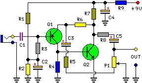
Build Your Own: Microphone Preamplifier Circuit (2mA)
Description
This circuit is primarily designed to furnish household stereo amplifiers alongside a microphone input. The battery power supply represents a sensible choice: in this manner, the input circuitry remains shielded from extraneous low-frequency noise picked up from the mains and connection to the amplifier is simplified, owing to the absence of a mains cable and power supply unit. Utilizing a stereo microphone, the circuit should be replicated twice. In this instance, two individual volume controls are preferable to a dual-gang stereo potentiometer. Minimal current consumption (approximately 2mA) assures a prolonged battery lifespan.
More about components
The operation of this circuit prominently features integrated circuits, offering a compact and efficient solution for amplification. Specifically, the circuit employs two bipolar junction transistors, the BC560 and BC550. These ICs are commonly utilized as general-purpose transistors, providing amplification capabilities in a single package. They are characterized by their relatively high current gain and moderate switching speeds, making them suitable for a variety of low-power amplifier applications. Their integration reduces the component count and simplifies the circuit design while maintaining performance.
Circuit Diagram:
Parts:
- P1 = 2.2K
- R1 = 100K
- R2 = 100K
- R3 = 100K
- R4 = 8.2K
- R5 = 68R
- R6 = 6.8K
- R7 = 1K
- R8 = 1K
- R9 = 150R
- C1 = 1uF-63V
- C2 = 100uF-25V
- C3 = 100uF-25V
- C4 = 100uF-25V
- C5 = 22uF-25V
- Q1 = BC560
- Q2 = BC550
Circuit Operation:
This circuit is founded upon a low-noise, high-gain two-stage PNP and NPN transistor amplifier, utilizing DC negative feedback through R6 to precisely stabilize operating conditions. The output signal’s level is attenuated by P1, simultaneously reducing the stage’s gain due to the increased value of R5. This unique connection of P1 facilitates the achievement of a high input headroom, permitting the circuit to accommodate a broad spectrum of input sources (0.2 to 200mV RMS for a 1V RMS output).
Notes:
- Harmonic distortion is approximately 0.1% @ 1V RMS output (across all frequencies).
- Maximum input voltage (level control cursor set at maximum) = 25mV RMS
- Maximum input voltage (level control cursor set at center position) = 200mV RMS
- Enclosing the circuit within a metal casing is strongly recommended.
- Connect the circuit’s output to your amplifier’s Aux input via a shielded cable and appropriate connectors.
