- Boost Your MP3 Power: 32 Ohm Amplifier Circuit
- Build Your 9V Bass Booster Circuit Diagram
- Build Your 20dB Audio Booster Circuit Diagram
- Symmetrical Class A Preamplifier – Build Your Audio Masterpiece
- Build Your Perfect Symmetrical 4 Channel Amplifier Circuit
- Build Your Ideal Buffer: Class A Circuit Diagram (560Ω)
- Discrete Preamplifier Circuit Diagram
- Build Your Own: Microphone Preamplifier Circuit (2mA)
- Stereo Preamplifier Circuit: Build Your +16dB Bass Boost
- Phono Preamplifier Circuit Diagram: 47K, 6.8K, 47nF Build!
- Modular Preamplifier Switching Center: Build Your Stereo Chain
- Portable Microphone Preamplifier Circuit Diagram – Build Your Own!
- Build Your Own Phono Preamplifier Circuit (18V)
- Amplify Signals: 741 Op-Amp Stethoscope Circuit Diagram
- Turn Speaker into Microphone: Build Your 6-12V Circuit
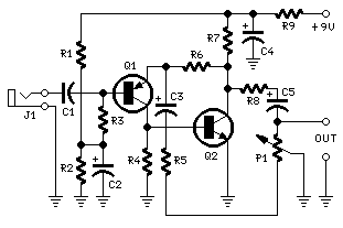
Portable Microphone Preamplifier Circuit Diagram – Build Your Own!
Circuit Diagram
Components:
- P1 2K2 Linear Potentiometer
- R1,R2,R3 100K 1/4W Resistors
- R4 8K2 1/4W Resistor
- R5 68R 1/4W Resistor
- R6 6K8 1/4W Resistor
- R7,R8 1K 1/4W Resistors
- R9 150R 1/4W Resistor
- C1 1uF 63V Polyester Capacitor
- C2,C3,C4 100uF 25V Electrolytic Capacitors
- C5 22uF 25V Electrolytic Capacitor
- Q1 BC560C 45V 100mA Low noise High gain PNP Transistor
- Q2 BC550C 45V 100mA Low noise High gain NPN Transistor
- J1 Jack socket (Mono 3 or 6 mm.)
Device Purpose:
This circuit is primarily intended to furnish common home stereo amplifiers alongside a microphone input. The battery supply represents a favorable compromise; in this manner, the input circuit remains immune to low-frequency interference from mains power and simplifies connections to the amplifier due to the absence of a mains cable and power supply.
When a stereo microphone is utilized, the circuit should be duplicated. In this case, two individual level controls are preferable to a dual-ganged stereo potentiometer. The circuit’s low current draw (approximately 2mA) ensures a prolonged battery lifespan.
Circuit Operation:
The circuit relies on a low-noise, high-gain two-stage PNP and NPN transistor amplifier, employing DC negative feedback through R6 to stabilize operating conditions with notable precision. The output level is attenuated by P1, concurrently reducing the stage gain due to the elevated value of R5. This distinctive arrangement of P1 yields a high input headroom, enabling it to manage a broad spectrum of input sources (0.2 to 200mV RMS for a 1V RMS output).
Notes:
- Harmonic distortion is around 0.1% @ 1V RMS output (all frequencies).
- Maximum input voltage (level control cursor set at maximum) = 25mV RMS
- Maximum input voltage (level control cursor set at center position) = 200mV RMS
- Enclosing the circuit within a metal casing is strongly recommended.
- Connect the device’s output to the Aux input of your amplifier using a shielded cable and suitable connectors.
circuit from http://www.redcircuits.com/
