- Boost Your MP3 Power: 32 Ohm Amplifier Circuit
- Build Your 9V Bass Booster Circuit Diagram
- Build Your 20dB Audio Booster Circuit Diagram
- Symmetrical Class A Preamplifier – Build Your Audio Masterpiece
- Build Your Perfect Symmetrical 4 Channel Amplifier Circuit
- Build Your Ideal Buffer: Class A Circuit Diagram (560Ω)
- Discrete Preamplifier Circuit Diagram
- Build Your Own: Microphone Preamplifier Circuit (2mA)
- Stereo Preamplifier Circuit: Build Your +16dB Bass Boost
- Phono Preamplifier Circuit Diagram: 47K, 6.8K, 47nF Build!
- Modular Preamplifier Switching Center: Build Your Stereo Chain
- Portable Microphone Preamplifier Circuit Diagram – Build Your Own!
- Build Your Own Phono Preamplifier Circuit (18V)
- Amplify Signals: 741 Op-Amp Stethoscope Circuit Diagram
- Turn Speaker into Microphone: Build Your 6-12V Circuit
Phono Preamplifier Circuit Diagram: 47K, 6.8K, 47nF Build!
Description
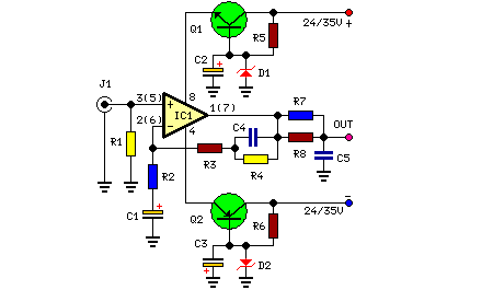
Over time, following the rise of digital media, analog records have largely vanished. However, a phono stage remains valuable for enjoying older vinyl recordings from a carefully preserved collection. This straightforward and effective circuit, specifically designed for inexpensive moving-magnet cartridges, can be connected with the audio amplification circuits showcased on these web pages. These amplifiers are characterized by reduced noise levels, a favorable RIAA frequency response curve, minimal distortion, and good high-frequency response thanks to passive equalization within the 1 to 20 KHz range.
Circuit Diagram:
Parts:
- R1 = 47K
- R2 = 100R
- R3 = 6.8K
- R4 = 68K
- R5 = 2.7K-1/2W
- R6 = 2.7K-1/2W
- R7 = 2.2K
- R8 = 39K
- C1 = 100uF-25V
- C2 = 100uF-25V
- C3 = 100uF-25V
- C4 = 47nF-63V
- C5 = 47nF-63V
- D1 = BZX79C18
- D2 = BZX79C18
- Q1 = BC337
- Q2 = BC327
- J1 = RCA Jack
- IC1 = LM833, Operational Amplifier
Integrated Circuit Details
The LM833 is a general-purpose operational amplifier commonly used in a wide variety of audio circuits. It possesses a high gain and a moderate bandwidth, making it suitable for amplifying signals and implementing various filter designs. Its low input bias current and input offset voltage contribute to low distortion in audio applications. The IC has a supply voltage range of -15V to +15V and can handle significant current loads without significant degradation in performance. Its popularity stems from its affordability and reliable performance across a broad range of audio frequencies. This operational amplifier offers a robust solution for amplifying audio signals while minimizing unwanted noise and distortion.
Notes:
- R2, R3, R4, R7, R8, C4 & C5 must be chosen with low tolerance specifications.
- The schematic depicts the left channel and the power supply circuitry.
- For stereo operation, R1, R2, R3, R4, R7, R8; J1; C1, C4 & C5 require doubling.
- The values in parentheses denote the IC1’s right channel circuitry.
