- Boost Your MP3 Power: 32 Ohm Amplifier Circuit
- Build Your 9V Bass Booster Circuit Diagram
- Build Your 20dB Audio Booster Circuit Diagram
- Symmetrical Class A Preamplifier – Build Your Audio Masterpiece
- Build Your Perfect Symmetrical 4 Channel Amplifier Circuit
- Build Your Ideal Buffer: Class A Circuit Diagram (560Ω)
- Discrete Preamplifier Circuit Diagram
- Build Your Own: Microphone Preamplifier Circuit (2mA)
- Stereo Preamplifier Circuit: Build Your +16dB Bass Boost
- Phono Preamplifier Circuit Diagram: 47K, 6.8K, 47nF Build!
- Modular Preamplifier Switching Center: Build Your Stereo Chain
- Portable Microphone Preamplifier Circuit Diagram – Build Your Own!
- Build Your Own Phono Preamplifier Circuit (18V)
- Amplify Signals: 741 Op-Amp Stethoscope Circuit Diagram
- Turn Speaker into Microphone: Build Your 6-12V Circuit
Stereo Preamplifier Circuit: Build Your +16dB Bass Boost
Description
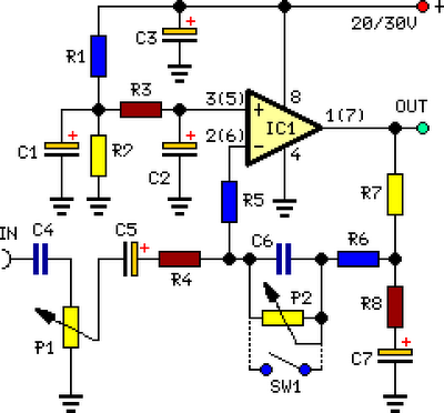
This preamplifier was crafted to accommodate CD players, tuners, and tape recorders, delivering an alternating current voltage amplification of 4, intended for driving less sensitive power amplifiers. Considering that contemporary high-fidelity home equipment often incorporates compact loudspeaker enclosures, a reduction in the lower bass frequency range is frequently observed. This circuit includes a bass enhancement feature, enabling compensation for this limitation. A variable resistor can be utilized to adjust the bass boost from 0 to a maximum of +16dB @ 30Hz. If a consistent, maximum boost value is required, the adjustable resistor may be replaced by a switch.
Circuit Diagram:
Parts:
- P1 = 10K
- P2 = 100K
- R1 = 100K
- R2 = 100K
- R3 = 15K
- R4 = 10K
- R5 = 22K
- R6 = 15K
- R7 = 1K
- R8 = 470R
- C1 = 2.2uF-25v
- C2 = 2.2uF-25v
- C3 = 470uF-35v
- C4 = 1uF-35V
- C5 = 2.2uF-25v
- C6 = 47nF-63v
- C7 = 22uF-25v
- IC1 = TL072, Operational Amplifier
- SW1 = DPST Switch
Integrated Circuit Details
TL072 Operational Amplifier
The TL072 is a dual operational amplifier, packaged in a single 8-pin IC. This amplifier offers high input impedance and low noise, making it suitable for a wide range of audio applications. The TL072 provides excellent performance for preamplifier circuits, offering stability and precision. Its features include low input bias current, low input offset current and low DC offset voltage, crucial for accurate amplification. The device is capable of operating over a broad temperature range and is shielded against external electrical noise. The TL072 is commonly utilized in audio circuits for amplification, filtering, and instrumentation.
Notes:
- The schematic demonstrates a single-channel implementation, while R1, R2, R3, and C1, C2, C3 are shared between both channels.
- For stereo operation, P1, P2 (or SW1), R4, R5, R6, R7, and R8, alongside C4, C5, C6, and C7, must be duplicated.
- Numbers within parentheses denote IC1's right channel pin connections.
- Employing a logarithmic type resistor for P2 assures a more consistent regulation of the bass boost.
- When a simple boost-in boost-out operation is required, P2 must be eliminated, and SW1 should be added as depicted in the diagram.
- For stereo operation, SW1 must be a DPST type.
- It is important to note that, utilizing SW1, the boost function is active when the switch is open and inactive when the switch is closed.
