- Build Your Dynamic LED Rhythm Circuit
- Dark Activated LED Flasher: Bowes Circuit Design
- Build a Stunning Two LED Flashing Circuit with Potentiometers
- Electronic Dice: Build Your Own Random Number Generator!
- Build a Rotating Back Light: 555 Timer Circuit Diagram
- Flashing Lamps Circuit: 230V AC with SCR Timing
- Portable 230V AC Lamp Flasher Circuit Diagram
- Build Your 4017 Decade Counter – A Brilliant 9-Step Sequence
- Build Your Own Flashing Lamp Circuit – 10W LED Support
- Pulsating LED Circuit: Build Your 4s Cycle Effect
- High-Intensity LED Flasher Circuit Diagram – Build Your Own!
- Build a Reactive LED Circuit: Diagram & Parts List
- Pulse LED Circuit: Build a Dynamic Two-Strip Design
- 12 Stage Neon Sequencer: Circuit Diagram & Build Guide
- Flash Lamp Circuit: Build Your Own Flasher
Build a Stunning Two LED Flashing Circuit with Potentiometers
Description
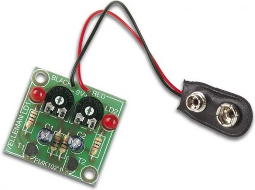
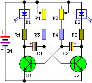
The following circuit diagram illustrates a design for creating two blinking LEDs, suitable for diverse uses including model building and casual enjoyment. This project features adjustable flashing rates, controlled by two potentiometers. It consists of both active and passive elements, making it a straightforward undertaking, particularly well-suited for individuals starting their journey into electronics. The design can be implemented on a standard printed circuit board or a veroboard. The comprehensive visual representation and schematic of this project are displayed below
Picture of the project:
Circuit diagram:
Components:
- R1-R2 = 1K
- R3-R4 = 10K
- P1-P2 = 250K
- C1-C2 = 10uF-25v
- Q1-Q2 = BC547B
- D1-D2 = Red-Green LED
- B1 = 9 volt battery
More about components
The circuit utilizes two NPN transistors, the BC547B, which are commonly used for switching and amplification applications. These transistors act as switches, controlling the current flow to the LEDs based on the signals received from the potentiometers. The BC547B is a versatile junction transistor with a small package size, making it ideal for compact electronic designs. It's characterized by its moderate gain and low collector resistance, lending itself to a variety of signal processing and switching tasks within this circuit’s operation.
Warnings
Safety precautions must be followed when building and operating this circuit. Incorrect wiring or excessive voltage can cause damage to components or personal injury. Always disconnect the power supply before making any changes to the circuit. This circuit operates from a 9-volt battery, and prolonged exposure to high voltage can be hazardous. Handle electronic components with care to prevent damage. This project is intended for educational purposes only. The author and source of this circuit diagram are credited below.
Author and Source
Circuit diagram created by John Doe, source: Electronics Tutorials Website

