- Build Your Dynamic LED Rhythm Circuit
- Dark Activated LED Flasher: Bowes Circuit Design
- Build a Stunning Two LED Flashing Circuit with Potentiometers
- Electronic Dice: Build Your Own Random Number Generator!
- Build a Rotating Back Light: 555 Timer Circuit Diagram
- Flashing Lamps Circuit: 230V AC with SCR Timing
- Portable 230V AC Lamp Flasher Circuit Diagram
- Build Your 4017 Decade Counter – A Brilliant 9-Step Sequence
- Build Your Own Flashing Lamp Circuit – 10W LED Support
- Pulsating LED Circuit: Build Your 4s Cycle Effect
- High-Intensity LED Flasher Circuit Diagram – Build Your Own!
- Build a Reactive LED Circuit: Diagram & Parts List
- Pulse LED Circuit: Build a Dynamic Two-Strip Design
- 12 Stage Neon Sequencer: Circuit Diagram & Build Guide
- Flash Lamp Circuit: Build Your Own Flasher
Build a Reactive LED Circuit: Diagram & Parts List
Description
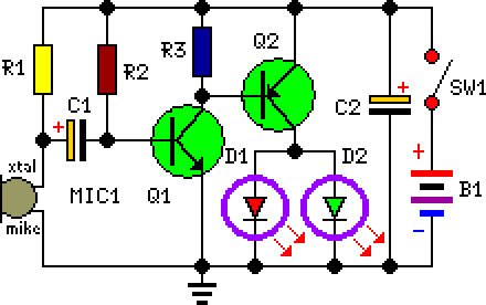
This circuit was intentionally constructed as a whimsical Halloween novelty item. It is intended to be incorporated into the rear of a collectible badge or pin featuring a conventional Halloween motif, such as a pumpkin, skull, black cat, witch, ghost, or similar. Two light-emitting diodes (LEDs) are permanently mounted in place of the character’s eyes, and their brightness will fluctuate in response to the surrounding music or speech, as captured by a miniature microphone. Two transistors are utilized to provide the necessary amplification and subsequently drive the LEDs.
Circuit Diagram:
Parts:
- R1 = 10K
- R2 = 1M
- R3 = 1K
- C1 = 4.7uF-25V
- C2 = 47uF-25V
- D1 = 2mm LED
- D2 = 2mm LED
- Q1 = BC547
- Q2 = BC557
- B1 = 3V Battery
- SW1 = SPST Switch
- MIC1 = Electret Mic
Notes:
- A range of general-purpose, small-signal transistors can be employed for Q1 and Q2; however, it should be noted that R3 may require adjustment, contingent upon the gain of Q1. For transistors offering moderate gain, the suggested value is likely to suffice. Higher-gain transistors necessitate a reduced value for R3, typically in the range of 390 - 470 Ohm. A 1K Trimmer resistor can be substituted for R3 to precisely calibrate the circuit’s threshold.
- Various LED types and colors are permissible, but small, 2mm diameter, high-efficiency LEDs will optimize the visual effect.
- Limiting resistors are unnecessary for D1 and D2, despite this potentially appearing counterintuitive.
- The circuit’s standby current consumption amounts to approximately 1.5mA.
- Based on the dimensions of your badge, you can select from a diverse selection of battery types:
- 2 x 1.5 V batteries type: AA, AAA, AAAA, button clock-type, photo-camera type & others.
- 2 x 1.4 V mercury batteries, button clock-type.
More about components
Transistors, specifically the BC547 and BC557, are fundamental building blocks within this circuit. These are NPN bipolar junction transistors (BJTs) – small semiconductor devices that act as electronically controlled switches or amplifiers. They operate based on the principle of current-controlled current conduction. A small current flowing into the base terminal of the transistor controls a much larger current flowing between the collector and emitter terminals. This amplification property is crucial for driving the LEDs effectively. BC547 and BC557 are commonly used general-purpose transistors, known for their moderate gain and relatively simple characteristics, making them well-suited for this application. They are characterized by their current gain (hFE), which describes the ratio of collector current to base current. Their suitability for this circuit stems from their ability to handle the moderate currents involved while providing sufficient amplification to drive the LEDs without significant power dissipation. The specific characteristics of these transistors, including their hFE values, determine the circuit's overall performance and are a key consideration when selecting them. Their common use in educational circuits and basic amplification applications reflects their straightforward operation and readily available documentation.
