- Build Your Dynamic LED Rhythm Circuit
- Dark Activated LED Flasher: Bowes Circuit Design
- Build a Stunning Two LED Flashing Circuit with Potentiometers
- Electronic Dice: Build Your Own Random Number Generator!
- Build a Rotating Back Light: 555 Timer Circuit Diagram
- Flashing Lamps Circuit: 230V AC with SCR Timing
- Portable 230V AC Lamp Flasher Circuit Diagram
- Build Your 4017 Decade Counter – A Brilliant 9-Step Sequence
- Build Your Own Flashing Lamp Circuit – 10W LED Support
- Pulsating LED Circuit: Build Your 4s Cycle Effect
- High-Intensity LED Flasher Circuit Diagram – Build Your Own!
- Build a Reactive LED Circuit: Diagram & Parts List
- Pulse LED Circuit: Build a Dynamic Two-Strip Design
- 12 Stage Neon Sequencer: Circuit Diagram & Build Guide
- Flash Lamp Circuit: Build Your Own Flasher
Dark Activated LED Flasher: Bowes Circuit Design
Description
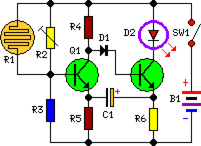
This circuit utilizes a distinctive Bowes/White emitter-coupled multivibrator design. The oscillating frequency is approximately 1Hz and is controlled via the value of component C1. The illumination of the photodiode initiates the blinking action when the light level is significantly low. The precise starting point of the flashing can be fine-tuned by adjusting resistor R2.
Circuit Diagram:
Parts:
- R1 = LDR
- R2 = 100K
- R3 = 10K
- R5 = 470R
- R6 = 47R
- R4 = 10K
- C1 = 220uF-25V
- D1 = 1N4148
- D2 = LED any type (see notes)
- Q1 = BC337
- Q2 = BC337
- B1 = 3V Battery or 2x1.5V cells in series
- SW1 = SPST Switch
Notes:
- Optimal flashing frequency results are typically achieved when C1 is selected within a range of 100 to 1000µF.
- For driving a incandescent lamp, the following modifications are recommended:
- A 2.2 to 3V, 250-300mA bulb should be substituted for the LED.
- R2 = 10K 1/2W Trimmer Cermet
- R3, R4 = 1K 1/4W Resistors
- R6 = 1R 1/4W Resistor
- C1 = 470 to 1000µF 25V Electrolytic Capacitor
- In LED-mode operation, the current draw during standby is less than 400µA.
- In Lamp-mode operation, the standby current is approximately 3mA.
More about components
The circuit incorporates two BC337 transistors, acting as active components within the multivibrator design. These transistors, commonly known as NPN bipolar junction transistors, facilitate the switching action that governs the oscillating behavior of the circuit. The BC337 is a general-purpose transistor frequently employed in amateur radio circuits and various electronic projects due to its ease of use and reasonable performance characteristics. These transistors amplify and switch electronic signals, playing a crucial role in determining the timing and oscillation patterns of the circuit.
