- Build Your Dynamic LED Rhythm Circuit
- Dark Activated LED Flasher: Bowes Circuit Design
- Build a Stunning Two LED Flashing Circuit with Potentiometers
- Electronic Dice: Build Your Own Random Number Generator!
- Build a Rotating Back Light: 555 Timer Circuit Diagram
- Flashing Lamps Circuit: 230V AC with SCR Timing
- Portable 230V AC Lamp Flasher Circuit Diagram
- Build Your 4017 Decade Counter – A Brilliant 9-Step Sequence
- Build Your Own Flashing Lamp Circuit – 10W LED Support
- Pulsating LED Circuit: Build Your 4s Cycle Effect
- High-Intensity LED Flasher Circuit Diagram – Build Your Own!
- Build a Reactive LED Circuit: Diagram & Parts List
- Pulse LED Circuit: Build a Dynamic Two-Strip Design
- 12 Stage Neon Sequencer: Circuit Diagram & Build Guide
- Flash Lamp Circuit: Build Your Own Flasher
Portable 230V AC Lamp Flasher Circuit Diagram
Description
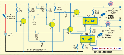
Here is a portable, high-power incandescent electric lamp flasher. It constitutes a dual flasher (alternating blinker) capable of handling two separate 230V AC loads (bulbs L1 and L2). The circuit is entirely transistorised and battery-powered. The free-running oscillator circuit is constructed using two low-power, low-noise transistors T1 and T2. One of these transistors is consistently conducting, while the other remains inactive.
Due to regular charging and discharging of capacitors C1 and C2, the two transistors cycle between conducting and non-conducting states. The collector of transistor T1 is connected to the base of driver transistor T4 via a current-limiting resistor R5. Likewise, the collector of transistor T2 is connected to the base of driver transistor T3 through a limiting resistor R6. These transistors are utilized to trigger Triac1 and Triac2 (each BT136) through optotriacs IC1 and IC2, respectively, and switch on the power supply to external loads L1 and L2.
IC1 and IC2 – Optotriacs
Optotriacs IC1 and IC2 are crucial components in this circuit. These integrated circuits (ICs) are specifically designed to provide electrical isolation between the low-voltage control circuitry and the high-voltage AC loads (bulbs L1 and L2). They function as optically-controlled switches. When the base current of the optotriac is sufficient, the phototransistor within the IC becomes forward-biased, allowing current to flow between the collector and emitter, effectively switching on the corresponding Triac (BT136). This isolation protects the sensitive control circuitry from potentially damaging voltage spikes or surges present in the AC mains. These ICs are typically packaged as dual-channel optotriacs, offering two independent switching paths.
IC1 and IC2 – Triacs
Triacs, specifically BT136, are three-terminal semiconductor devices that can control AC power. They are used here to switch the 230V AC loads (L1 and L2) on and off. A triac is essentially a three-directional AC switch. They are triggered by the optotriacs (IC1 and IC2) when a sufficient base current is applied. The base current from the optotriacs causes the triac to conduct, allowing current to flow through the AC load (bulb L1 or L2), thereby illuminating the bulb. When the base current ceases, the triac turns off, cutting off the power to the bulb.
Circuit diagram:
IC1 and IC2 operate at a low frequency determined by the values of capacitors C1 and C2. The oscillator circuit built around transistors T1 and T2 generates these low frequencies. When transistor T3 conducts, IC1 is enabled to drive Triac1 and bulb L1 glows. Similarly, when transistor T4 conducts, IC2 is enabled to drive Triac2 and bulb L2 glows. Connect the power supply line (L) of mains to bulbs L1 and L2, and neutral (N) to T1 terminals of Triac1 and Triac2.
You can also connect neutral (N) line of the external 230V mains supply to both loads (bulbs L1 and L2) as a common line and then route supply line (L) to respective loads (bulbs L1 and L2). The circuit works off only 3 volts. Since current consumption is fairly low, two AA-type cells are sufficient to power the circuit. Assemble the circuit on a general-purpose PCB and enclose in a suitable plastic cabinet with integrated AA-size pen-light cell holder. Drill holes for mounting the ‘on’/‘off’ switch and power switching terminals. Also connect two bulb holders for bulbs L1 and L2.
EFY note:
While assembling, testing or repairing, take care to avoid the lethal electric shock.
