- Build Your Dynamic LED Rhythm Circuit
- Dark Activated LED Flasher: Bowes Circuit Design
- Build a Stunning Two LED Flashing Circuit with Potentiometers
- Electronic Dice: Build Your Own Random Number Generator!
- Build a Rotating Back Light: 555 Timer Circuit Diagram
- Flashing Lamps Circuit: 230V AC with SCR Timing
- Portable 230V AC Lamp Flasher Circuit Diagram
- Build Your 4017 Decade Counter – A Brilliant 9-Step Sequence
- Build Your Own Flashing Lamp Circuit – 10W LED Support
- Pulsating LED Circuit: Build Your 4s Cycle Effect
- High-Intensity LED Flasher Circuit Diagram – Build Your Own!
- Build a Reactive LED Circuit: Diagram & Parts List
- Pulse LED Circuit: Build a Dynamic Two-Strip Design
- 12 Stage Neon Sequencer: Circuit Diagram & Build Guide
- Flash Lamp Circuit: Build Your Own Flasher
Pulse LED Circuit: Build a Dynamic Two-Strip Design
Description
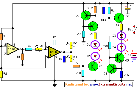
This circuit implements two LED strips operating in a pulsating manner, where one strip transitions from an off state through a gradual brightening phase, followed by a gradual dimming phase, and so on, while the opposing strip performs the reverse process. Each individual strip can be constructed using between two and five LEDs, utilizing a 9V power supply. The two operational amplifiers contained within IC1 function as a triangular wave generator. The upward and downward voltage signals originating from pin #7 of IC1 drive two complementary circuits built around a constant current source (Q1, Q2, Q5, and Q6), each supported by a driver transistor (Q3 and Q6). The timing characteristics of the overall circuit are controlled by components R4, R5, and C1; the total duration of each cycle can be adjusted by modifying their respective values. R7 and R8 regulate the intensity of the LEDs’ illumination.
Circuit diagram:
Parts:
- R1, R2 _______________ 4.7K 1/4W Resistors
- R3 _______________ 22K 1/4W Resistor
- R4 _______________ 3M9 1/4W Resistor (See Notes)
- R5 _______________ 2M2 1/4W Carbon Trimmer (See Notes)
- R6, R10, R11, R14, R15 _______________ 10K 1/4W Resistors
- R7, R8 _______________ 100K 1/4W Carbon Trimmers (See Notes)
- R9, R13 _______________ 47K 1/4W Resistors
- R12, R16 _______________ 56R 1/4W Resistors
- C1 _______________ 1µF 63V Polyester Capacitor
- C2 _______________ 100µF 25V Electrolytic Capacitor
- D1-D4 etc. _______________ 5 or 3mm. LEDs (any type and color) (See Notes)
- IC1 _______________ LM358 Low Power Dual Op-amp
- Q1, Q2, Q4 _______________ BC327 45V 800mA PNP Transistors
- Q3, Q5, Q6 _______________ BC337 45V 800mA NPN Transistors
- SW1 _______________ SPST miniature Slider Switch
- B1 _______________ 9V PP3 Battery / Clip for PP3 Battery
Notes:
- To circumvent the need for trimmer potentiometers, recommended values for a 9V supply are: R4=3M9, R9 & R13=47K, and the trimmers should be replaced with a short connection.
- If a wall-plug adapter is preferred instead of a 9V battery, the circuit can be powered at 12V, permitting the use of up to 6 LEDs per strip, or at 15V, allowing for up to 7 LEDs per strip.
- In scenarios where trimmer potentiometers R7 and R8 are utilized, their values should be adjusted to 100K.
