- Build Your Dynamic LED Rhythm Circuit
- Dark Activated LED Flasher: Bowes Circuit Design
- Build a Stunning Two LED Flashing Circuit with Potentiometers
- Electronic Dice: Build Your Own Random Number Generator!
- Build a Rotating Back Light: 555 Timer Circuit Diagram
- Flashing Lamps Circuit: 230V AC with SCR Timing
- Portable 230V AC Lamp Flasher Circuit Diagram
- Build Your 4017 Decade Counter – A Brilliant 9-Step Sequence
- Build Your Own Flashing Lamp Circuit – 10W LED Support
- Pulsating LED Circuit: Build Your 4s Cycle Effect
- High-Intensity LED Flasher Circuit Diagram – Build Your Own!
- Build a Reactive LED Circuit: Diagram & Parts List
- Pulse LED Circuit: Build a Dynamic Two-Strip Design
- 12 Stage Neon Sequencer: Circuit Diagram & Build Guide
- Flash Lamp Circuit: Build Your Own Flasher
Pulsating LED Circuit: Build Your 4s Cycle Effect
Description
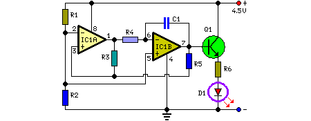
This circuit drives an LED in a pulsating fashion, specifically, the LED transitions between an off state, gradually illuminates, and then dims progressively, and so on. This specific operational mode is achieved through a triangular wave generator, utilizing two operational amplifiers housed within a remarkably economical 8-pin Dual In-Line (DIL) case integrated circuit. Q1 serves as a current buffer, intended to enhance the driving capacity of the connected load. The values of R4 and C1 establish the timing parameters; according to the component list, the overall duration of each cycle is approximately 4 seconds.
Circuit diagram:
Parts:
- R1 = 4.7K
- R2 = 4.7K
- R3 = 22K
- R4 = 2.2M
- R5 = 10K
- R6 = 47R
- C1 = 1µF-63V
- Q1 = BC337
- D1 = Red Led
- IC1 = LM358
Integrated Circuits Detail
The core of this circuit relies on the LM358, a versatile dual operational amplifier IC. This integrated circuit combines two independent op-amps on a single chip, offering increased functionality and efficiency. The LM358 is commonly used in low-power applications due to its low quiescent current consumption. It is a bipolar op-amp, meaning it utilizes both NPN and PNP transistors internally, providing a wider operating range and potentially better performance compared to some single-supply op-amps. Its dual nature allows for increased flexibility in circuit design and can be utilized for various signal processing tasks. The LM358 is a widely available and cost-effective solution for many electronic projects.
Notes:
- Optimal outcomes are generally obtained when R4’s value falls within a range of 220K to 4.7MΩ.
- When R4's value is lower than 220KΩ, the pulsing effect becomes virtually indistinguishable from a simple blinking operation.
- The LED can be any type or color, providing a wide range of aesthetic options.
- A filament lamp bulb can be substituted for the LED, provided it is rated between 3.2V and 6V, with a maximum current draw of 200mA.
- If a bulb is utilized as the load, R6 must be omitted from the circuit.
- The voltage supply’s range can be effectively utilized between 4V and 6V; 4.5V represents the most suitable compromise.
- It is crucial not to exceed 6V for the circuit’s power supply, as this will compromise its performance, and potentially damage Q1 when a bulb is used as the load.
- At a 6V supply, increase the value of R6 to 100Ω.
