- Build Your Dynamic LED Rhythm Circuit
- Dark Activated LED Flasher: Bowes Circuit Design
- Build a Stunning Two LED Flashing Circuit with Potentiometers
- Electronic Dice: Build Your Own Random Number Generator!
- Build a Rotating Back Light: 555 Timer Circuit Diagram
- Flashing Lamps Circuit: 230V AC with SCR Timing
- Portable 230V AC Lamp Flasher Circuit Diagram
- Build Your 4017 Decade Counter – A Brilliant 9-Step Sequence
- Build Your Own Flashing Lamp Circuit – 10W LED Support
- Pulsating LED Circuit: Build Your 4s Cycle Effect
- High-Intensity LED Flasher Circuit Diagram – Build Your Own!
- Build a Reactive LED Circuit: Diagram & Parts List
- Pulse LED Circuit: Build a Dynamic Two-Strip Design
- 12 Stage Neon Sequencer: Circuit Diagram & Build Guide
- Flash Lamp Circuit: Build Your Own Flasher
Build Your Knightrider Scanner: 555 & 4017 Circuit Diagrams
Description
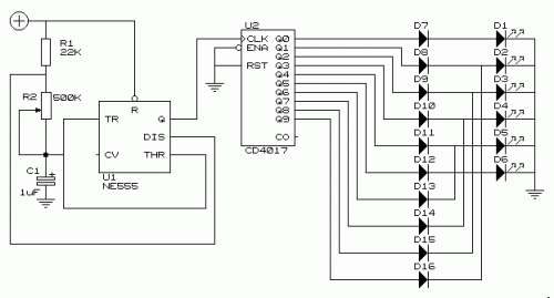
This uncomplicated circuit operates a set of six LEDs, replicating the functionality of a 'Knightrider scanner' mode. The energy usage is primarily determined by the particular LEDs chosen, specifically if a 555 (555 CMOS version) is implemented.
Circuit diagram
It is important to note that the VDD and GND connections for the integrated circuits are not depicted within the schematic drawing.
Pin-outs:
- (7)555
- 1 GND
- 2 TRIGGER
- 3 OUTPUT
- 4 RESET
- 5 CONTROL VOLTAGE
- 6 THRESHOLD
- 7 DISCHARGE
- 8 VDD
- (4017)
- 1 Q5
- 2 Q1
- 3 Q0
- 4 Q2
- 5 Q6
- 6 Q7
- 7 Q3
- 8 GND
- 9 Q8
- 10 Q4
- 11 Q9
- 12 CO
- 13 NOT ENABLE
- 14 CLK
- 15 RESET
- 16 VDD
555 Timer
The 555 timer is a versatile integrated circuit commonly utilized as a timing circuit, oscillator, or flip-flop. Its CMOS construction provides low power consumption and excellent stability. This particular 555 is the 555 (555 CMOS version), a popular choice for building a variety of circuits, including pulse generators and oscillators. The 555 timer operates with either positive or negative voltage supplies, offering flexibility in circuit design. It's a highly reliable component with a wide range of applications in electronics.
4017 Decade Counter
The 4017 is a decade counter integrated circuit. It's a versatile device commonly used to count from 0 to 9. This particular 4017 is the 4017, a common IC used for decimal counting and digital displays. The 4017 operates using binary counting, sequentially advancing through each decimal digit. It’s a widely used component in educational electronics projects and digital circuits.
circuit from http://www.xs4all.nl/~odu/
