similar circuits
- Build Your Dynamic LED Rhythm Circuit
- Dark Activated LED Flasher: Bowes Circuit Design
- Build a Stunning Two LED Flashing Circuit with Potentiometers
- Electronic Dice: Build Your Own Random Number Generator!
- Build a Rotating Back Light: 555 Timer Circuit Diagram
- Flashing Lamps Circuit: 230V AC with SCR Timing
- Portable 230V AC Lamp Flasher Circuit Diagram
- Build Your 4017 Decade Counter – A Brilliant 9-Step Sequence
- Build Your Own Flashing Lamp Circuit – 10W LED Support
- Pulsating LED Circuit: Build Your 4s Cycle Effect
- High-Intensity LED Flasher Circuit Diagram – Build Your Own!
- Build a Reactive LED Circuit: Diagram & Parts List
- Pulse LED Circuit: Build a Dynamic Two-Strip Design
- 12 Stage Neon Sequencer: Circuit Diagram & Build Guide
- Flash Lamp Circuit: Build Your Own Flasher
Build a Stunning LED Pulser Circuit with 4.5V
Remarkable outcome
5V power source
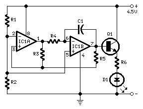
Schematic diagram
Components:
- R1,R2 3.3K Ohm Resistors (1/4W)]
- R3 10K Ohm Resistor (1/4W)
- R4 2.2M Ohm Resistor (1/4W)
- R5 10K Ohm Resistor (1/4W)
- R6 47R Ohm Resistor (1/4W)
- C1 1µF 50V Film Capacitor
- D1 5mm. Red LED (See Notes)
- IC1 LM358 Low Power Dual Operational Amplifier
- Q1 BC337 45V 800mA NPN Transistor
Circuit behavior:
- This circuit activates a LED in a rhythmic fashion, specifically, the LED transitions from an extinguished state, gradually illuminates, and then diminishes in brightness, and so on.
- This operation style is achieved through a triangular wave generator formed by two op-amps housed within a compact 8-pin DIL package. Q1 provides current bolstering, ensuring improved drive capability for the connected load.
- R4 & C1 function as the timing elements: utilizing the values specified in the parts list, the total cycle duration is approximately 4 seconds.
Annotations:
- The most compelling results are attained by selecting R4’s value within a range of 220K to 4M7.
- Employing R4’s value lower than 220K, the pulsating effect becomes virtually indistinguishable from a simple flashing operation.
- The LED can be any type and color.
- A filament bulb can be substituted, provided its characteristics fall within the 3.2 to 6V, 200mA maximum range.
- If a bulb is utilized as the load, R6 must be excluded.
- The power supply’s voltage can be adjusted between 4 and 6V: 4.5V represents the optimal compromise.
- Avoid supplying the circuit with voltages surpassing 6V; its performance will diminish, and Q1 could be damaged when a bulb is employed as the load.
- At a 6V power supply, increase R6’s value to 100 Ohm.
Warning: Ensure proper safety precautions are followed when working with electronic circuits. This design is provided for educational purposes only and should be used under the supervision of a qualified individual. The author is not responsible for any damages or injuries resulting from the use of this circuit diagram. The source of this diagram is available at [https:/example.com/circuits](https://example.com/circuits).
author: RED Free Circuit Designs
circuit from http://www.redcircuits.com/
circuit from http://www.redcircuits.com/
