- Build Your Dynamic LED Rhythm Circuit
- Dark Activated LED Flasher: Bowes Circuit Design
- Build a Stunning Two LED Flashing Circuit with Potentiometers
- Electronic Dice: Build Your Own Random Number Generator!
- Build a Rotating Back Light: 555 Timer Circuit Diagram
- Flashing Lamps Circuit: 230V AC with SCR Timing
- Portable 230V AC Lamp Flasher Circuit Diagram
- Build Your 4017 Decade Counter – A Brilliant 9-Step Sequence
- Build Your Own Flashing Lamp Circuit – 10W LED Support
- Pulsating LED Circuit: Build Your 4s Cycle Effect
- High-Intensity LED Flasher Circuit Diagram – Build Your Own!
- Build a Reactive LED Circuit: Diagram & Parts List
- Pulse LED Circuit: Build a Dynamic Two-Strip Design
- 12 Stage Neon Sequencer: Circuit Diagram & Build Guide
- Flash Lamp Circuit: Build Your Own Flasher
Build a Stunning LED or Lamp Sequencer Circuit
This text presents a remarkably simple and adaptable modular design.
There are no limitations regarding the number of modules incorporated within the loop.
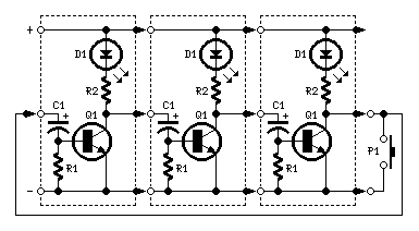
Circuit Diagram Utilizing LEDs:
Components:
- R1 1.05 kΩ 1/4W Resistor
- R2 6.80 kΩ 1/4W Resistor (Optional, see text)
- C1 47 µF 25V Electrolytic Capacitor
- D1 LED any type
- Q1 BC337 45V 800mA NPN Transistor
- P1 SPST Pushbutton
- LP1 Filament Lamp 12 or 24V (See text)
Comments:
The primary objective of this circuit is to establish a ring where LEDs or Lamps illuminate in a sequential manner. A key feature of this design is its high adaptability; it’s possible to construct a loop containing any number of LEDs or Lamps, with each illuminating device operating on its own small circuit.
The diagrams depict three-stage circuits for illustrative purposes; an unlimited number of stages can be added, provided the output of the final stage is returned to the input of the initial stage, as shown.
The function of P1, the SPST pushbutton, is to provide a guaranteed initiation of the sequence at power-on. However, when a significant number of stages are utilized, it also enables the simultaneous illumination of multiple LEDs or Lamps, for example, one device illuminated and three others, and so on.
Upon power-on, P1 should be maintained closed until only the LED or Lamp associated with the module to which the pushbutton is connected remains steadily illuminated. When P1 is released, the sequencer commences; briefly pushing P1 after the sequence has begun allows for the implementation of various sequences, contingent upon the total number of stages used.
Notes:
- If one LED per module is used, the voltage supply can range from 6 to 15V.
- Multiple LEDs can be connected in series per module; the supply voltage must correspond to their number.
- With a 24V supply (the maximum permissible voltage), approximately 10 LEDs wired in series can be connected to each module, roughly 7 at 15V and no more than 5 at 12V.
- The precise number of LEDs can vary, depending on their color and required brightness.
- When utilizing lamps, the voltage supply can range from 9 to 24V. The lamp voltage must always be equal to the supply voltage.
- Lamps can also be wired in series, such as four 6V lamps connected in series and powered by a 24V supply.
- Should you intend to employ lamps drawing more than 400mA, BC337 transistors should be replaced by Darlington types like BD677, BD679, BD681, 2N6037, 2N6038, 2N6039 etc.
- Due to the built-in Base-Emitter resistor typically present within Darlington transistors, R1 may be omitted, further reducing the number of components.
- The sequencer’s speed can be modified by altering the value of C1.
- A similar design was documented in print approximately forty years ago. This design utilized germanium transistors and low-voltage lamps. The use of LEDs, silicon transistors, Darlington transistors, and a 24V supply represents a significant advancement.
circuit from http://www.redcircuits.com/
