- Build Your Dynamic LED Rhythm Circuit
- Dark Activated LED Flasher: Bowes Circuit Design
- Build a Stunning Two LED Flashing Circuit with Potentiometers
- Electronic Dice: Build Your Own Random Number Generator!
- Build a Rotating Back Light: 555 Timer Circuit Diagram
- Flashing Lamps Circuit: 230V AC with SCR Timing
- Portable 230V AC Lamp Flasher Circuit Diagram
- Build Your 4017 Decade Counter – A Brilliant 9-Step Sequence
- Build Your Own Flashing Lamp Circuit – 10W LED Support
- Pulsating LED Circuit: Build Your 4s Cycle Effect
- High-Intensity LED Flasher Circuit Diagram – Build Your Own!
- Build a Reactive LED Circuit: Diagram & Parts List
- Pulse LED Circuit: Build a Dynamic Two-Strip Design
- 12 Stage Neon Sequencer: Circuit Diagram & Build Guide
- Flash Lamp Circuit: Build Your Own Flasher
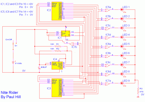
Nite Rider Lights: Circuit Diagram with 9 Bright LEDs
Circuit Diagram
The circuit is represented on PCB 123, obtainable without charge from: http://www.pcb123.com
As a dedicated cyclist, I am consistently seeking innovative solutions for enhanced visibility during nighttime rides. I desired a unique, attention-grabbing device to capture the attention of drivers. Observing the rear illumination systems of other cyclists, I conceived the idea of 'NITE-RIDER'. This incorporates nine exceptionally bright LEDs, arranged in a continuous flow from left to right and right to left. It’s possible to implement this design utilizing red LEDs for rear-mounted applications or white LEDs for a powerful, noticeable visual element on the front of the bicycle. All integrated circuits employed are CMOS devices, permitting operation with a 9V PP3 battery while maintaining a very low current draw to maximize operational longevity.
Integrated Circuits Details
The core of this circuit relies on several integrated circuits, each contributing to its functionality. The primary integrated circuits are CMOS devices, optimized for low power consumption and compatibility with a 9V PP3 battery. These devices facilitate the creation of a robust and reliable illumination system.
4027 Flip Flop IC1
The 4027 flip-flop is a versatile integrated circuit used to create bistable multivibrators, which are fundamental building blocks in digital logic circuits. Its ability to switch between two stable states makes it ideal for implementing switching functions within the 'NITE-RIDER' circuit, acting as a switch to enable either the IC2 or IC3 at pin 13. This controlled switching is essential for managing the sequence of the LED illumination.
4017 Decade Counter IC2 and IC3
The 4017 decade counter is a popular integrated circuit frequently used for counting sequences of decimal numbers. In this circuit, the 4017 decade counters IC2 and IC3 are employed to generate a timed sequence, driving the illumination of the LEDs. Each counter accurately increments its decimal value, providing a precise and controlled method for sequencing the LEDs’ activation, with Q9 of the counter being monitored at pin 11 for enabling of the OR gates.
4071 OR Gate IC5, IC6 and IC7
The 4071 OR gate is a fundamental integrated circuit used to implement logical OR operations. In this design, three 4071 OR gates (IC5, IC6 and IC7) are used to protect the outputs of the counters IC2 and IC3, preventing potential damage to the LED circuit. These gates ensure that the LED outputs are only energized when the counters are functioning correctly, enhancing the system’s reliability and safety. The energized outputs are fed to the anodes of the LEDs 1 to 9.
Parts
- 1 555 timer IC4.
- 1 4027 flip flop IC1.
- 2 4017 Decade Counter IC2 and IC3.
- 3 4071 OR gate IC5, IC6 and IC7.
- 1 470 Ohm resistor 1/4 watt R3.
- 2 10K resistors 1/4 watt R1 and R2.
- 1 6.8UF Capacitor 16V C1.
- 9 Super bright LED's 1 to 9.
- 1 9V PP3 Battery.
- 1 single pole switch SW1.
- 1 Box.
How The Circuit Works.
- IC4, C1, R1 and R2 are used for the clock pulse which is fed to both the counters IC2 and IC3 Pin 14.
- IC1 is a Flip Flop and is used as a switch to enable ether IC2 or IC3 at pin 13.
- IC7a detects when ether IC2 or IC3 has reached Q9 of the counter pin 11.
- IC5, IC6 and IC7a protects the outputs of the counters IC2 and IC3 using OR gates which is then fed to the Anodes of the
- LED's 1 to 9.
