similar circuits
- Build Your Dynamic LED Rhythm Circuit
- Dark Activated LED Flasher: Bowes Circuit Design
- Build a Stunning Two LED Flashing Circuit with Potentiometers
- Electronic Dice: Build Your Own Random Number Generator!
- Build a Rotating Back Light: 555 Timer Circuit Diagram
- Flashing Lamps Circuit: 230V AC with SCR Timing
- Portable 230V AC Lamp Flasher Circuit Diagram
- Build Your 4017 Decade Counter – A Brilliant 9-Step Sequence
- Build Your Own Flashing Lamp Circuit – 10W LED Support
- Pulsating LED Circuit: Build Your 4s Cycle Effect
- High-Intensity LED Flasher Circuit Diagram – Build Your Own!
- Build a Reactive LED Circuit: Diagram & Parts List
- Pulse LED Circuit: Build a Dynamic Two-Strip Design
- 12 Stage Neon Sequencer: Circuit Diagram & Build Guide
- Flash Lamp Circuit: Build Your Own Flasher
High Power Strobe Circuit Diagram – 20Hz Flash
Description
This design incorporates a significantly enhanced “horseshoe” Xenon tube, generating increased illumination. Furthermore, the flash frequency can be adjusted up to approximately 20Hz. Caution is advised; direct observation of the flash tube whilst the device is active is strongly discouraged!
Circuit Diagram
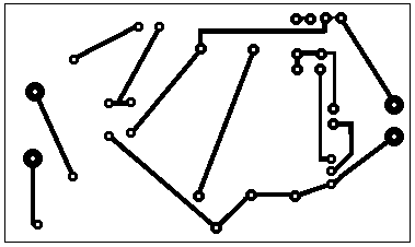
Printed Circuit Board Layout
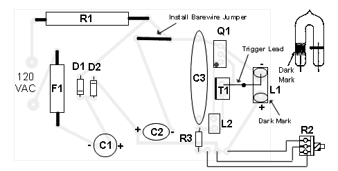
Component Placement
Components
- R1 250 Ohm, a resistor with a 10 Watt rating.
- R2 500K Potentiometer.
- R3 680K, a 1/4 Watt resistor.
- D1, D2 1N4004 Silicon Diodes.
- C1, C2 22 uF, 350V Capacitors.
- C3 0.47uF, a 400 Volt Mylar Capacitor.
- T1 4KV Trigger Transformer (refer to “Notes”).
- L1 Flash Tube (refer to “Notes”).
- L2 Neon Bulb.
- Q1 106 SCR.
- F1 115V 1A Fuse.
- Various Case, Wiring, Cord, Knob for R2.
Notes
- T1 and L1 are obtainable from The Electronics Goldmine.
- This circuit is not insulated from ground; exercise caution when operating without a protective enclosure. An enclosure is mandatory for normal operation. Avoid any contact with circuit parts with the case open or when the enclosure is absent.
- Numerous diodes exceeding 250 volts at a 1-amp rating can be substituted for the 1N4004 diodes.
- Prolonged operation at high flash rates (exceeding approximately 30 seconds) may cause overheating of C1 and C2, potentially leading to their failure.
- The schematic does not include a switch; however, the addition of one is, of course, possible.
circuit from http://www.electronics-lab.com/


