- Build Your Dynamic LED Rhythm Circuit
- Dark Activated LED Flasher: Bowes Circuit Design
- Build a Stunning Two LED Flashing Circuit with Potentiometers
- Electronic Dice: Build Your Own Random Number Generator!
- Build a Rotating Back Light: 555 Timer Circuit Diagram
- Flashing Lamps Circuit: 230V AC with SCR Timing
- Portable 230V AC Lamp Flasher Circuit Diagram
- Build Your 4017 Decade Counter – A Brilliant 9-Step Sequence
- Build Your Own Flashing Lamp Circuit – 10W LED Support
- Pulsating LED Circuit: Build Your 4s Cycle Effect
- High-Intensity LED Flasher Circuit Diagram – Build Your Own!
- Build a Reactive LED Circuit: Diagram & Parts List
- Pulse LED Circuit: Build a Dynamic Two-Strip Design
- 12 Stage Neon Sequencer: Circuit Diagram & Build Guide
- Flash Lamp Circuit: Build Your Own Flasher
Build Your Own Triple Stroboscope Circuit Design
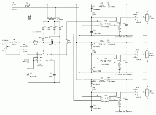
Circuit diagram
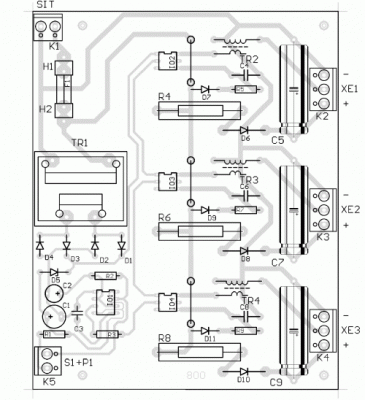
This circuit facilitates the observation of movement relative to other stroboscopes. The generation of a rectangular signal is achieved through the use of the NE555 integrated circuit. This design necessitates a low-voltage power supply, constructed utilizing a simple transformer TR1, a traditional rectifier bridge, and a zener diode. The NE555 operates in a multivibrator mode, producing astable pulses ranging from 2Hz to 20Hz. The frequency can be adjusted via potentiometer P1. Potentiometer P1 can be positioned remotely up to 30 meters away, allowing for remote operation of the stroboscope. While readily available components such as R1, R2, R3, R4, R6, R8, R5, R7, R9, P1, C1, C2, C3, C4, C6, C8, C5, C7, C9, D1, D2, D3, D4, D5, D6, D7, D8, D9, D10, D11, IO1, IO2, IO3, IO4, XE1, XE2, XE3, F1, K1, K5, K2, K3, K4, S1 are commonly found in electronic stores, sourcing the transformers TR2, TR3, TR4 might prove more challenging. It is crucial to exercise extreme caution when handling this circuit, as high voltages are present across C5, C7, and C9.
Parts
- R1 = 6,8 k
- R2 = 5,6 k
- R3 = 330
- R4,R6,R8 = 270 / 5 W
- R5,R7,R9 = 220 k
- P1 = 100 k linear potentiometer
- C1 = 100 uF / 16 V
- C2 = 4,7 uF / 16 V
- C3 = 10 nF
- C4,C6,C8 = 22 nF / 400 V, MKS
- C5,C7,C9 = 10 uF / 350 V, electrolytic (high quality)
- TR1 = Standard transformer 230 V / 9 V, 1,5 VA
- TR2,TR3,TR4 = stroboscope transformer np (ZTK200)
- D1,D2,D3,D4 = 1N4149
- D5 = BZX85V Zener 3.9
- D6,D7,D8,D9,D10,D11 = 1N4004
- IO1 = NE555
- IO2,IO3,IO4 = MOC3020
- XE1,XE2,XE3 = stroboscope lamps FT50
- F1 = Fuse 0.8 A, 20 mm
- K1,K5 = connectors ARK200-2
- K2,K3,K4 = connectors ARK200-3
- S1 = Switch
The NE555 is a versatile three-terminal integrated circuit widely employed as a voltage-controlled oscillator, signal-coupled device, and timer. It’s a bipolar junction transistor (BJT) integrated circuit, commonly utilized in circuits requiring stable frequency generation. Its three pins – Pin 1 (Emitter), Pin 2 (Collector), and Pin 4 (Base) – allow for various configurations. The IC’s stability and relatively low cost have made it a staple in numerous electronic applications. This IC facilitates the production of stable, predictable pulses, crucial for the function of the stroboscope circuit.


