- Build Your Dynamic LED Rhythm Circuit
- Dark Activated LED Flasher: Bowes Circuit Design
- Build a Stunning Two LED Flashing Circuit with Potentiometers
- Electronic Dice: Build Your Own Random Number Generator!
- Build a Rotating Back Light: 555 Timer Circuit Diagram
- Flashing Lamps Circuit: 230V AC with SCR Timing
- Portable 230V AC Lamp Flasher Circuit Diagram
- Build Your 4017 Decade Counter – A Brilliant 9-Step Sequence
- Build Your Own Flashing Lamp Circuit – 10W LED Support
- Pulsating LED Circuit: Build Your 4s Cycle Effect
- High-Intensity LED Flasher Circuit Diagram – Build Your Own!
- Build a Reactive LED Circuit: Diagram & Parts List
- Pulse LED Circuit: Build a Dynamic Two-Strip Design
- 12 Stage Neon Sequencer: Circuit Diagram & Build Guide
- Flash Lamp Circuit: Build Your Own Flasher
1.5V LED Flashers: Build Circuits with Timing & Voltage Doubling
Description
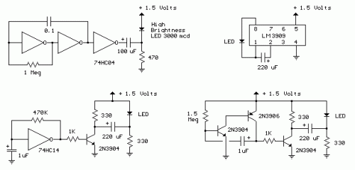
The LED flashing circuits presented below function utilizing a solitary 1.5 volt battery. The scheme situated on the upper right employs the frequently-used LM3909 LED flasher integrated circuit and necessitates solely a timing capacitor and an LED.
The uppermost left circuit, conceived by Andre De-Guerin, demonstrates the use of a 100µF capacitor to amplify the battery voltage, achieving 3 volts for the LED. Two segments of a 74HC04 hex inverter are utilized as a squarewave oscillator that governs the flashing frequency, while a third section serves as a buffer, charging the capacitor in series with a 470 ohm resistor, with the buffer output maintaining a +1.5 volts level. Upon the buffer output transitioning to ground (zero volts), the charged capacitor is connected in series with the LED and the battery, providing sufficient voltage to illuminate the LED. The LED current is approximately 3 mA, recommending a high-brightness LED.
In the remaining two circuits, the same voltage-doubling method is implemented with the inclusion of a transistor, permitting the capacitor to discharge more rapidly and supplying a higher current (approximately 40 mA peak). An increased capacitor (1000µF) in series with a 33 ohm resistor would extend the flash duration to about 50mS. The separate three-transistor circuit at the lower right would require a resistor (around 5K) in series with the 1µF capacitor to broaden the pulse width.
