- Build a 4.7V USB Mobile Phone Charger Circuit
- Build Your 9V Ni-Cad Battery Charger Circuit
- Build Your Own NiCd Charger: 5V Circuit Design
- Build Your 5V USB Charger Circuit Today!
- Build Your 1.5V Pen Cell Mobile Charger Circuit
- Build Your Own 7.2V Mobile Charger Circuit
- Build a 3.6-6V Cellphone Charger Circuit
- Universal Battery Charger Circuit Diagram – Build Yours!
- Lithium-Polymer Peak Charger: Build Your 600mA Charging Circuit
- SLA Battery Charger Circuit: 2-Step Charging & Safety Features
- Battery Charger Regulator Circuit Diagram – 8V Design
- Build a Safe & Smart 5.6V Charger Circuit
- 12V Car Battery Charger: Build Your Constant Current Circuit
- Micropower Battery Protector Circuit Diagram for 4-10 Cell Batteries
- Build a Stunning Battery Status LED Flasher Circuit
Build a Stunning Battery Status LED Flasher Circuit
Alerting When a Circuit Battery Reaches Its End, 5V to 12V Operating Voltage
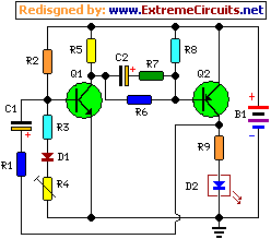
A Battery-status Indicator circuit proves beneficial, primarily for monitoring portable test instruments and similar devices. The LED D1 flashes to draw attention to the situation, preventing unintentional prolonged operation. The circuit generates approximately two LED flashes per second, with an average current consumption of around 200µA. Transistors Q1 and Q2 are configured as a non-common complementary astable multivibrator: both remain inactive almost continuously, activating only when the LED illuminates, contributing to minimal current usage.
Circuit Operation
This circuit functions with power supply voltages spanning from 5 to 12V. The LED flashing can be adjusted to the desired battery termination voltage (situated within the 4.8 to 9V range) by modifying Trimmer R4. Slight variations in the values of R3 and/or R4 can accommodate these changes. As the battery voltage approaches its depletion level, the LED flashing frequency decreases abruptly, alerting the user. Naturally, once the battery voltage drops below this threshold, the LED will remain permanently extinguished. To maintain stability of the battery depletion voltage, diode D1 was incorporated to compensate for variations in the Q1 Base-Emitter junction due to temperature changes. The utilization of a Schottky-barrier device (such as BAT46, 1N5819, or similar) for D1 is essential; the circuit will not operate if a standard silicon diode like the 1N4148 is used in its place.
Circuit Diagram
Components
- R1 = 220Ω - 1/4W Resistor
- R2 = 120kΩ - 1/4W Resistor
- R3 = 5.6kΩ - 1/4W Resistor
- R4 = 5kΩ - 1/2W Trimmer Cermet
- R5 = 33kΩ - 1/4W Resistor
- R6 = 680kΩ - 1/4W Resistor
- R7 = 220Ω - 1/4W Resistor
- R8 = 100kΩ - 1/4W Resistor
- R9 = 180Ω - 1/4W Resistor
- C1 = 4.7µF - 25V Electrolytic Capacitors
- C2 = 4.7µF - 25V Electrolytic Capacitors
- Q1 = BC547 - 45V 100mA NPN Transistor
- Q2 = BC557 - 45V 100mA PNP Transistor
- B1 = 5V to 12V Battery supply
- D1 = BAT46 - 100V 150mA Schottky-barrier Diode
- D2 = LED - Red 5mm.
Note
Further reduction in the circuit's average current consumption can be achieved by increasing the values of R1, R7, and R9.
