- Build a 4.7V USB Mobile Phone Charger Circuit
- Build Your 9V Ni-Cad Battery Charger Circuit
- Build Your Own NiCd Charger: 5V Circuit Design
- Build Your 5V USB Charger Circuit Today!
- Build Your 1.5V Pen Cell Mobile Charger Circuit
- Build Your Own 7.2V Mobile Charger Circuit
- Build a 3.6-6V Cellphone Charger Circuit
- Universal Battery Charger Circuit Diagram – Build Yours!
- Lithium-Polymer Peak Charger: Build Your 600mA Charging Circuit
- SLA Battery Charger Circuit: 2-Step Charging & Safety Features
- Battery Charger Regulator Circuit Diagram – 8V Design
- Build a Safe & Smart 5.6V Charger Circuit
- 12V Car Battery Charger: Build Your Constant Current Circuit
- Micropower Battery Protector Circuit Diagram for 4-10 Cell Batteries
- Build a Stunning Battery Status LED Flasher Circuit
Build a Safe & Smart 5.6V Charger Circuit
Description
Many portable chargers lack inherent current/voltage control or short-circuit safeguards. These chargers typically deliver raw 6-12V DC for powering battery packs. Commonly, mobile phone battery packs are rated at 3.6V, 650mAh. To maximize battery longevity, gradual charging at reduced currents is recommended. A charging time of six to ten hours at a current of 150-200mA is a suitable approach. This minimizes battery heat generation and prolongs its operational lifespan.
Integrated Circuit – CA3130
The CA3130 is a versatile three-channel operational amplifier IC. It is frequently utilized in power supply circuits due to its ability to amplify and filter signals. In this particular circuit, it's deployed to provide stable voltage regulation, contributing to the overall performance and reliability of the charger. It offers high gain, low noise, and excellent stability, essential characteristics for maintaining consistent output voltage levels.
Integrated Circuit – CA3130
The CA3130 serves as the core regulator within this circuit. Its operational amplifier functionality allows it to meticulously control the voltage delivered to the connected mobile phone. This precise regulation is critical for preventing damage to the phone’s delicate circuitry, ensuring safe and efficient charging. Its characteristics make it ideally suited for maintaining consistent output voltages, vital for reliable device charging.
Circuit Diagram
Parts:
- P1 = 10K LOG
- R1 = 1K
- R2 = 1K
- R3 = 1K
- R4 = 1K
- R5 = 3.3K
- R6 = 16R/2W
- R7 = 220R
- R8 = 3.3R
- R9 = 1K
- C1 = 470uF/25V
- C2 = 10uF/25V
- C3 = 1KuF/25V
- D1 = Red LED
- D2 = Green LED
- Q1 = BC547
- Q2 = BD677
- ZD1 = 12V/1W
- ZD2 = 5.6V/1W
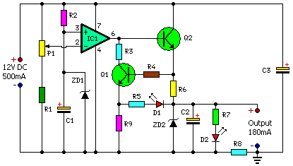
This circuit configuration provides approximately 180mA at 5.6V, safeguarding the mobile phone from unpredictable voltage fluctuations arising from the power line. Consequently, the charger can remain ‘on’ overnight for battery replenishment. The circuit effectively protects both the mobile phone and the charger by immediately disconnecting the output upon detecting a voltage surge or a short-circuit within the battery pack or connector. This can be considered an intermediary device situated between the existing charger and the mobile phone.
The circuit incorporates features such as voltage and current regulation, over-current protection, and voltage cutoff at both high and low levels. A notable aspect of the circuit is a ten-second delay before activation when mains power is restored following a power failure. This delay shields the mobile phone from immediate voltage spikes. When a short-circuit occurs at the battery terminal, resistor R8 senses the excessive current, enabling Q1 to conduct and illuminate D1. The illumination of D2 signifies the charging mode, while the activation of D1 indicates a short-circuit or over-current condition.
The value of resistor R8 is crucial for achieving the desired current level for the cutoff operation. With the specified value of R8 (3.3 ohms), the current is 350 mA. Adjusting the charging current is possible by modifying the value of R7 using the ‘I=V/R’ equation. Fabricate the circuit on a common PCB and house it within a small plastic case. Connect the circuit between the output lines of the charger and the input pins of the mobile phone, adhering to correct polarity.
