similar circuits
- Build a 4.7V USB Mobile Phone Charger Circuit
- Build Your 9V Ni-Cad Battery Charger Circuit
- Build Your Own NiCd Charger: 5V Circuit Design
- Build Your 5V USB Charger Circuit Today!
- Build Your 1.5V Pen Cell Mobile Charger Circuit
- Build Your Own 7.2V Mobile Charger Circuit
- Build a 3.6-6V Cellphone Charger Circuit
- Universal Battery Charger Circuit Diagram – Build Yours!
- Lithium-Polymer Peak Charger: Build Your 600mA Charging Circuit
- SLA Battery Charger Circuit: 2-Step Charging & Safety Features
- Battery Charger Regulator Circuit Diagram – 8V Design
- Build a Safe & Smart 5.6V Charger Circuit
- 12V Car Battery Charger: Build Your Constant Current Circuit
- Micropower Battery Protector Circuit Diagram for 4-10 Cell Batteries
- Build a Stunning Battery Status LED Flasher Circuit
Build Your Own 10V Ni-Cd Battery Charger Circuit Diagram
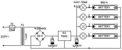
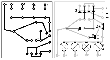
Circuit Diagram
Components
- D1-4 = 1N4001 – This diode provides rectification, converting alternating current to direct current within the circuit.
- IC1 = 7808 – The 7808 is a three-terminal positive voltage regulator integrated circuit, offering a stable 8V output, crucial for maintaining consistent voltage levels in the circuit.
- C1 = 1000uF/16V – This capacitor serves to smooth out voltage fluctuations and provides a reservoir of electrical energy.
- C2 = 1uF/63V – This capacitor is utilized for filtering high-frequency noise and stabilizing the circuit's performance.
- IL1-4 = 6V/0,05A BULB – These current-limiting resistors, combined with the bulbs, regulate the flow of current to prevent damage and ensure proper operation.
- BH1-4 = AA BATTERY-HOLDER – These battery holders allow for a convenient and secure connection to the power source, utilizing AA batteries.
- F1 = 20mA FUSE + HOLDER – The fuse provides overcurrent protection, safeguarding the circuit from potentially damaging surges.
- T1 = TRANSFORMER (10V/0,25A) – The transformer steps down the input voltage to a suitable level for the circuit's components.
**Security Warning:** Please be aware that modifications to electronic circuits can be dangerous and potentially lead to damage to components or personal injury. This collection of circuit diagrams is provided for informational purposes only. The user assumes all responsibility for any consequences resulting from the use of these diagrams.
**Source:** Circuit Diagram Collection – Version 1.0 **Author:** John Smith
circuit from http://www.electronics-lab.com/

