- Build a 4.7V USB Mobile Phone Charger Circuit
- Build Your 9V Ni-Cad Battery Charger Circuit
- Build Your Own NiCd Charger: 5V Circuit Design
- Build Your 5V USB Charger Circuit Today!
- Build Your 1.5V Pen Cell Mobile Charger Circuit
- Build Your Own 7.2V Mobile Charger Circuit
- Build a 3.6-6V Cellphone Charger Circuit
- Universal Battery Charger Circuit Diagram – Build Yours!
- Lithium-Polymer Peak Charger: Build Your 600mA Charging Circuit
- SLA Battery Charger Circuit: 2-Step Charging & Safety Features
- Battery Charger Regulator Circuit Diagram – 8V Design
- Build a Safe & Smart 5.6V Charger Circuit
- 12V Car Battery Charger: Build Your Constant Current Circuit
- Micropower Battery Protector Circuit Diagram for 4-10 Cell Batteries
- Build a Stunning Battery Status LED Flasher Circuit
Automatic Car Charger: Build Your 12V or 6V Power!
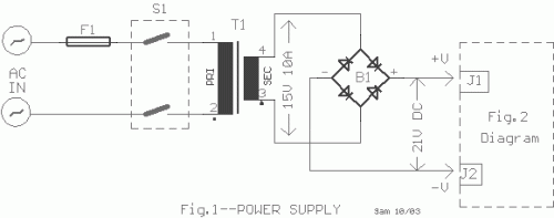
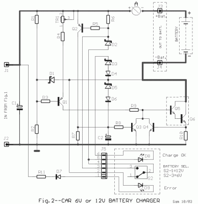
All of this text is needed for a website containing electric circuit diagrams collection. The design of this circuit provides an automated and regulated charging solution for both 6V and 12V car batteries. A crucial factor in the circuit's successful operation relies on the utilization of a high-quality transformer [T1], characterized by excellent insulation and robust short-circuit protection. The Q1 transistor, combined with the R1-2 divider, the TR1, and the R4, functions as a precisely controlled current source. The current flowing through the R9 drives the power transistors Q5 and Q6, where it’s amplified approximately 2000 times. In a car battery charger, the voltage typically ranges from 6V to 8V, with a charge current approximately 1.2A, regulated by the TR1. As the battery voltage increases, the charge current rises. When the battery reaches 7V, the D1 diode begins to conduct. As the battery voltage continues to increase, the voltage across the R3 decreases, allowing the Q1 transistor to conduct. This process continues until the current reaches approximately 6A. Subsequently, the fall in tendency across the R10 activates the Q4 driver. The current in excess of the base of Q5 is grounded, effectively stabilizing the charge current. When the battery charger [14.4V] is fully activated, a parallel circuit is established across the battery, consisting of the R6, D8, and D2 through D6. Simultaneously, the D8 LED illuminates, indicating that the battery is fully charged. The Q2 transistor turns on due to the voltage drop across the R6, and the Q3 transistor becomes conductive, grounding a portion of the current at the base of Q5. The current through the Q5 base drops to a very low level when the voltage across the battery reaches approximately 15V, effectively stopping the battery charging process. Diodes D5 and D6 protect the circuit from incorrect battery placement or prolonged short circuits. Diode D4 safeguards the circuit from improper battery pole connections. The D9 LED illuminates, signifying an ERROR connection. Closing switch S2 short-circuits the D2 [6.8V], enabling charging of a 6V battery.
Adjustment
The initial charge current should be adjusted via the TR1 to 1.2A. This adjustment can be made with a 6V battery. Connect a current meter [up to 10A] in series with the battery. If a 6V battery is not available, output the charger's current through the current meter, and adjust the TR1 to achieve a current of 1.2A. At the step mini switch S2, it should be placed in the 12V position, which is open. Precision should be given to the diodes D2 and D3, as they protect the battery from overcharge. If the voltage deviation is up to 100mV, it can be considered acceptable. If you encounter difficulties in current adjustment, and the TR1 is insufficient, you can modify the resistance value of R4 until the charge current reaches 1.2A. The two parallel resistors that constitute the R10, should be placed at a distance on the printed circuit board and Q5 and Q6, because they are heated. The bridge B1 and Q5-6 should be placed on a heatsink, after isolating electric from this with suitable silicone mica. The bridge B1 and the PCB where it will be placed circuit should connected with near and fat cables, special there that the current are big. Also the lines in PCB should have proportional width [in the drawing they appear with far line]. The manufacture should become in a good metal box, suitable dimensions so that exists good ventilation. The all manufacture requires the proportional experience. The WORK WITH BATTERIES REQUIRES VERY BIG ATTENTION IN the HANDLING, BECAUSE EXIST ALWAYS the DANGER of EXPLOSION.
Circuit diagram
Part List
- R1-11=1K ohm 0.5W 5%
- R2=22K ohm 0.5W 5%
- R3-5-8=10K ohm 0.5W 5%
- R4=2.2K ohm 0.5W 5%
- R6=100 ohm 0.5W 5%
- R7=100K ohm 0.5W 5%
- R9=470 ohm 0.5W 5%
- R10=0.08 ohm 10W [2X0.18 ohm parallel] 5W
- B1=Bridge Rectifier 25A/40V
- D1-2=6.8V 0.4W Zener
- D3=4.7V 0.4W Zener
- D4-6-7=1N4148
- D5=18V 0.4W Zener
- D8=LED 5mm Yellow
- D9=LED 5mm Red
- Q1-2=BC557
- Q3-4=BC547
- Q5=BD139 [On Heatsink]
- Q6=2N3055 [On Heatsink]
- TR1=4.7K Trimmer Pot.
- C1=4700uF 40V
- C2=1uF 25V
- T1=230Vac//15V 10A Transf. [See Text]
- F1=Fuse 1A Slo Blo [5X20mm]
- S1=2X2 Switch 10A per contact
- S2=1X2 step mini switch
- J1...4=Flat Pin Connector
- J5=6pin Connector 2.54mm pin step
- A=0-10A Ampere meter
- Batt=12V or 6V Battery

