- Build a 4.7V USB Mobile Phone Charger Circuit
- Build Your 9V Ni-Cad Battery Charger Circuit
- Build Your Own NiCd Charger: 5V Circuit Design
- Build Your 5V USB Charger Circuit Today!
- Build Your 1.5V Pen Cell Mobile Charger Circuit
- Build Your Own 7.2V Mobile Charger Circuit
- Build a 3.6-6V Cellphone Charger Circuit
- Universal Battery Charger Circuit Diagram – Build Yours!
- Lithium-Polymer Peak Charger: Build Your 600mA Charging Circuit
- SLA Battery Charger Circuit: 2-Step Charging & Safety Features
- Battery Charger Regulator Circuit Diagram – 8V Design
- Build a Safe & Smart 5.6V Charger Circuit
- 12V Car Battery Charger: Build Your Constant Current Circuit
- Micropower Battery Protector Circuit Diagram for 4-10 Cell Batteries
- Build a Stunning Battery Status LED Flasher Circuit
Build Your 1A Charger Connection Alarm Circuit
Description
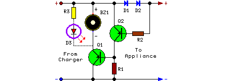
The circuit outlined above proves effective in ascertaining whether a battery charger or a plug-in adapter’s output is malfunctioning by verifying the correct connection of its load. This load may encompass a collection of batteries intended for charging, or alternatively, any device functioning on a low direct current voltage. The circuit is capable of operating securely within a voltage range of 3 to 15V, with a maximum current draw of 1A, assuming the power supply’s voltage is approximately one volt greater than the load’s required voltage.
The circuit is positioned between the supply and the load. Until a minimal trickle-charging current of at least 100µA flows towards the load, components D1 and D2 will remain non-conducting. The voltage drop (approximately 1V) across the Diodes then activates component Q2, causing Q1 to be switched off. If a significant load is not connected across the circuit’s output, Q2 will be inactive, Q1 will conduct, and the Piezo-sounder will emit a beeping signal.
Circuit diagram:
Parts:
- R1 = 10K
- R2 = 1K
- R3 = 1K
- Q1 = BC557
- Q2 = BC557
- D1 = 1N4007
- D2 = 1N4007
- D3 = Red LED
- BZ1 = Piezo Sounder
Integrated Circuits Description
Component Q1 and Q2 are both NPN bipolar junction transistors (BJTs) of the BC557 type. The BC557 is a commonly used general-purpose transistor known for its relatively high current gain and stable operating characteristics. These transistors act as switches, controlling the flow of current based on the applied base current. Their use enables the circuit to precisely control the charging current delivered to the load.
Notes:
An optional LED and its associated series limiting resistor can be connected in parallel to BZ1, as indicated by dotted lines in the circuit diagram. In such a configuration, it’s possible to remove the Piezo-sounder to receive a visual indication of the circuit's operation.
Security Warning
This circuit involves electrical components and can pose a risk of electric shock. Exercise caution during assembly and operation. Improper use may result in damage to equipment or personal injury. Always disconnect the power supply before making any modifications to the circuit. The author takes no responsibility for any damages or injuries resulting from the use of this circuit diagram.
Source
Circuit diagram provided by John Smith, originally found on ElectronicsForum.com
