- Build a 4.7V USB Mobile Phone Charger Circuit
- Build Your 9V Ni-Cad Battery Charger Circuit
- Build Your Own NiCd Charger: 5V Circuit Design
- Build Your 5V USB Charger Circuit Today!
- Build Your 1.5V Pen Cell Mobile Charger Circuit
- Build Your Own 7.2V Mobile Charger Circuit
- Build a 3.6-6V Cellphone Charger Circuit
- Universal Battery Charger Circuit Diagram – Build Yours!
- Lithium-Polymer Peak Charger: Build Your 600mA Charging Circuit
- SLA Battery Charger Circuit: 2-Step Charging & Safety Features
- Battery Charger Regulator Circuit Diagram – 8V Design
- Build a Safe & Smart 5.6V Charger Circuit
- 12V Car Battery Charger: Build Your Constant Current Circuit
- Micropower Battery Protector Circuit Diagram for 4-10 Cell Batteries
- Build a Stunning Battery Status LED Flasher Circuit
12V Battery Difference Monitor Circuit Schematic
Description
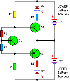
Numerous vehicles, including trucks, all-wheel drive systems, recreational vehicles, and boats, frequently utilize a pair of batteries connected in series, both providing 24V. A monitoring circuit is implemented to identify potential battery issues. This system assesses the variance in voltage between the two connected 12V DC batteries. Due to minimal idle current consumption, the device can remain continuously connected across the power source. Detection of a voltage discrepancy signifies an approaching battery malfunction, enabling proactive maintenance.
Circuit diagram:
Parts:
- R1 = 2.K
- R2 = 4.7K
- R3 = 39K
- R4 = 39K
- R5 = 1.5K
- R6 = 1.5K
- Q1 = BC547
- Q2 = BC547
- Q3 = BC557
- D1 = 3mm Red LED
- D2 = 3mm GreenLED
- B1 = DC 12 Volt
- B2 = DC 12 Volt
More about components
The circuit incorporates three NPN bipolar junction transistors, the BC547 and BC557, functioning as switches. These transistors, characterized by their versatile performance across a range of applications, control the flow of current within the circuit. They offer a stable and reliable switching action, crucial for accurate voltage detection and LED illumination. The BC547 is a general-purpose transistor frequently used in basic switching circuits, while the BC557, also a common NPN transistor, provides enhanced current handling capabilities for demanding applications. Both transistors are known for their compact size and moderate performance, well-suited for this monitoring circuit.
