- Build a 4.7V USB Mobile Phone Charger Circuit
- Build Your 9V Ni-Cad Battery Charger Circuit
- Build Your Own NiCd Charger: 5V Circuit Design
- Build Your 5V USB Charger Circuit Today!
- Build Your 1.5V Pen Cell Mobile Charger Circuit
- Build Your Own 7.2V Mobile Charger Circuit
- Build a 3.6-6V Cellphone Charger Circuit
- Universal Battery Charger Circuit Diagram – Build Yours!
- Lithium-Polymer Peak Charger: Build Your 600mA Charging Circuit
- SLA Battery Charger Circuit: 2-Step Charging & Safety Features
- Battery Charger Regulator Circuit Diagram – 8V Design
- Build a Safe & Smart 5.6V Charger Circuit
- 12V Car Battery Charger: Build Your Constant Current Circuit
- Micropower Battery Protector Circuit Diagram for 4-10 Cell Batteries
- Build a Stunning Battery Status LED Flasher Circuit
9V Battery Saver Circuit: Smart Power Control
Description
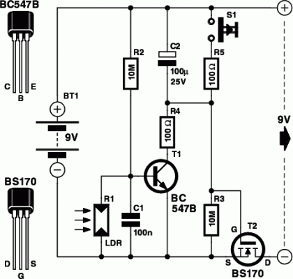
This is a small electronic switch that connects a power source to equipment for a specific duration when a button is pressed briefly. Furthermore, the ambient light level is also considered; the switch is deactivated if it’s dark, even if the delay period hasn’t elapsed. The circuit design is relatively uncomplicated. The switch itself utilizes a commonly employed MOSFET, namely the BS170.
A MOSFET (T2 within the circuit) employed in this configuration doesn't require a current to activate it (only a voltage), resulting in an efficient circuit. When the battery is initially connected to the power-saving circuit, capacitor C2 provides a positive voltage to the MOSFET’s gate, which causes T2 to conduct and subsequently connects the load (on the 9 V output) to the battery (BT1). C2 gradually charges up via R3 (i.e., the voltage across C2 increases).
Integrated Circuit Information
MOSFETs, such as the BS170, are three-terminal semiconductor devices used for switching and amplifying electronic signals. They operate based on the principle of controlling current flow between two of their terminals (source and drain) using a voltage applied to the third terminal (gate). They are widely used in electronic circuits due to their fast switching speeds, low on-resistance, and compatibility with integrated circuits. The BS170 is a general-purpose MOSFET, commonly used in switching applications.
Circuit diagram:
This causes the voltage at the gate to drop and eventually becomes so low that T2 can no longer conduct, removing the supply voltage to the load. In this state, the battery saver circuit consumes a minimal current of approximately 1 µA. If the button S1 is now pressed, C2 will discharge, and the circuit returns to its initial state, establishing a new turn-off delay. Resistor R5 is used to regulate the discharge current through the switch to a safe level. Only holding the switch down for a few hundredths of a second is sufficient to fully discharge C2.
Within our prototype, connected between a 9 V battery and a load that drew about 5 mA, the output voltage began to decline after approximately 26 minutes. After 30 minutes, the voltage had decreased to 2.4 V. It's recommended to use a high-quality capacitor for C2 (one with a very low leakage current), otherwise, the switch may take an extended period to deactivate! The ambient light level is detected using an LDR (R1). An LDR is a type of light sensor that increases its resistance as the light level rises. We advise using an FW150, obtainable from e.g. Conrad as part number 183547-89.
When there's insufficient light, its resistance increases, and the potential divider R1/R2 causes transistor T1 to conduct. T1 then rapidly charges up C2 through R4, limiting the current to a safe level. This prevents T2 from conducting, and the load is deactivated. The value chosen for R2 determines the minimum darkness level required for T1 to begin conducting. The power-saving circuit can be integrated into devices using 6 or 9 volt batteries and which draw no more than 100 mA. The circuit can be constructed on an experimenter’s board and should be designed as compactly as possible for incorporation into battery-powered devices.
